Continue to Site

Eng-Tips is the largest engineering community on the Internet

Intelligent Work Forums for Engineering Professionals

  • Congratulations KootK on being selected by the Eng-Tips community for having the most helpful posts in the forums last week. Way to Go!

Structural integrity of a welded steel stand for two condenser units 8

Status
Not open for further replies.

Parker87

Computer
Aug 4, 2020
23
I've recently bought two mini split heat pumps and want to build a stand to hold the outdoor units. I would like to obtain an E-shaped cantilever structure but am unable to determine whether the beams will hold the units safely in place without adding some form of additional support (e.g. diagonal braces).
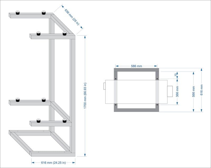
LG_U24_Stand_-_P_T_n5so5h.jpg


I plan to use 50mm x 50mm x 2mm (2" x 2" x 14ga) square steel tubes which are going to be welded together as shown in the drawing above. The small cylindrical shapes are rubber-metal mounts that will go underneath the condenser units to prevent vibrations from being transferred to the steel frame. I might also use some larger rubber-metal buffers to decouple the stand from the concrete foundation on which it will be mounted, so any unmitigated vibrations don't find their way into the nearby walls of the house.

The weight of the outdoor units is 43kg (95lb) each, and the way this weight is distributed on each corner is shown on page 11 of LG's product data book (i.e. page 13 of the PDF) linked below.


Since this stand is only going to be secured to the ground (and not to a wall), my main concern is stability, i.e., supporting the weight and stress from the two condensers without bending, breaking, or tipping over, while enduring the fluctuating weather conditions.

Any thoughts or advice would be greatly appreciated. 
 
Replies continue below

Recommended for you

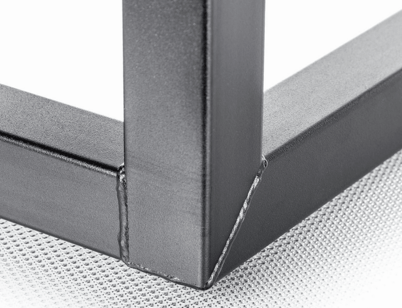
The bottom frame members are mitred together at each corner in a 2-way mitre. The post is square cut to sit on top. On the picture below, the post is to the left and we are seeing the underside of the base to the right.

I don't know anything about vibration isolation, so I won't comment on that.

If the top of stand can be supported laterally by a wall as suggested by retired13, that would be more positive than relying on the base connection alone.

image_vyarph.png


BA
 
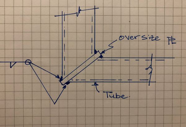
This is my preferred method for providing the corner of a tube frame if you can tolerate the extra plate sticking out - especially for thin tube (or for backyard welders).

corner_fnaaqq.jpg
 
I don't think welding HSS is an idea project for DIY. You'll need professional welder and pay the top dollar. With the unit fastened to the wall, put a thick rubber door mat beneath to get ride of vibration.
 
The consequences of failure are not life threatening, so I guess Parker87 is free to take his chances with abnormal lateral forces.

BA
 
retired13 said:
I don't think welding HSS is an idea project for DIY. You'll need professional welder and pay the top dollar.

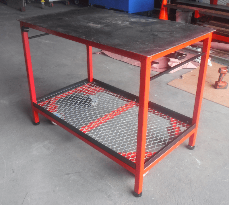
DIY of HSS is not too difficult, especially if your tube wall thickness is > 1/8" - provided you have the right equipment. I am a self-taught welder and built this mobile welding table in a few hours - 1.5" x 3/16" wall, square tube - very strong - supported many thousands of pounds of steel fab on this unit. Took me longer to paint it than to cut and weld it up. I hate painting!

WELD_TABLE_ximwzg.png
 
He's free with deep pocket, are we free of our obligation? His question turns out quite interesting, but it is still a DIY project, I prefer to draw a line somewhere....But it's up to anybody's judgement when to call end.
 
Ingenuity,

Good job, I couldn't have picked it out from professional works, but you would agree, it takes time and practice to be a capable welder, though the OP can be one too. I learnt soldering myself, however, it can not compare with electrode welding though.
 
The wall thickness in ingenuity great example makes it a better starter project. The other gauges discussed burn thru easily and it takes more skill. Aluminum takes far more skill and understanding of prep to weld well. What do you have for tools? If only a few, I would price out what you need as you could spend more than hiring someone. McMaster carr sells a number of fittings to make this easier, but they add up quickly. They have some that eliminate welding, but they are not as neat.

 
I had a recently retired architect friend of my parents look at my sketches and he said that if I use the 2"x 2" HSS, I won't need any supporting braces/struts and could probably do without the front corner posts in the bottom as well, because the load is very light. For the vibrations, he suggested I cut a rectangular hole in the concrete with a circular saw, dig out some soil and pour a new concrete slab that won't be touching the surrounding one. Anchor the verticals in the new concrete and drop the bottom frame, similarly to what BAretired suggested. But as I already said, I would rather not mess with the concrete as I would probably need to hire someone else to do it and wait for it to dry for weeks before I can mount the whole thing. And it's too close to the walls of the house, which might open a new can of worms.

I can get a local welder to execute the build, but I want to at least finalize the design (including the basic details of the welding process) myself.
 
..."retired architect friend of my parents"...hmmm, I am surprised he did not suggest you curve the steelwork and paint it mauve. :)


Great comment... I don't know, and I should. I have checked with Canadian Code S16 and CISC 'Handbook of Steel Construction' and couldn't find an answer. I posted the CISC a query about this.

Looking at the latest rendition... it looks like a Horse designed to military specs... aka Elephant.

Thanks

Dik
 
dik,

I like your comment. It is fool proof for DIY project.
 
Because I don't have sufficient space to put them side by side in the location I want to utilize. Clearance requirements suggest a lot of open space around them — they will have to be placed at least 1 meter apart and be clear of any surrounding obstacles.

Page 47 of the manual you linked says otherwise. If the units are outdoors and have only ground and one wall and no overhangs, the clearance requirement is more like 250 mm, minimum. This suggests that your upper unit does not need to be so high; eliminating 400 mm from the height would drastically reduce the tipping and bending concerns.

TTFN (ta ta for now)
I can do absolutely anything. I'm an expert! faq731-376 forum1529 Entire Forum list
 
Ingenuity... Mauve would be nice, or maybe candy apple green (the colour of my first bookcase that I made)... I'm thinking of a hammer-beam truss for the 'arms'...

Dik
 
IRstuff said:
...eliminating 400 mm from the height would drastically reduce the tipping and bending concerns.

Tipping, yes. Bending, not really. The problem with the outriggers supporting the units remains the same. They would still need more support than the two posts at the back.

BA
 
BART... have you actually run the moments?

Dik
 
IRstuff said:
Page 47 of the manual you linked says otherwise. If the units are outdoors and have only ground and one wall and no overhangs, the clearance requirement is more like 250 mm, minimum.

Good catch, but the normal/preferred clearance is actually 600mm, which is the minimum I would aim for.

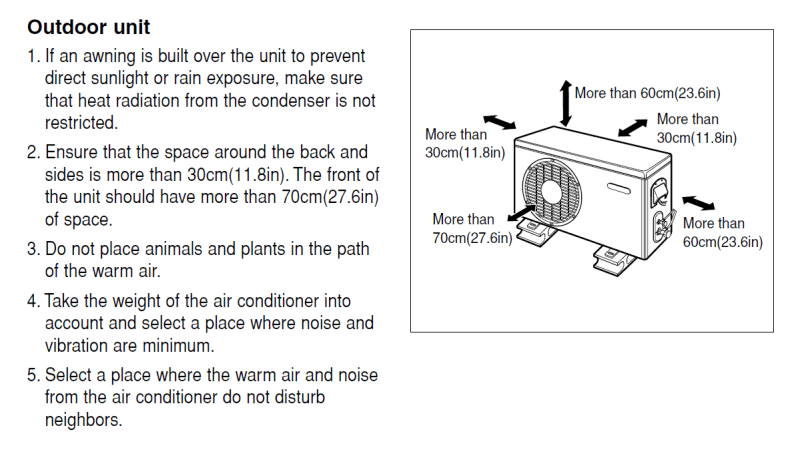
Page 10 of another, more generic LG manual (
LG_AC_Clearances_mgmsta.png


My '1 meter' claim was erroneous — I was adding up 30cm and 60cm and giving it an extra 10cm 'just to be safe' which was obviously a mistake.

IRstuff said:
This suggests that your upper unit does not need to be so high; eliminating 400 mm from the height would drastically reduce the tipping and bending concerns.

No, the 250mm-600mm figures are for the sides only. The top clearance should be greater than 600mm as shown in the picture above, or 1000mm if there are surrounding walls like in Case 1 in the other manual. (That is, unless I'm missing something.)
 
If I use the rubber mounting feet and raise the frame a couple of centimeters off the ground, I might be able to go with a simpler design, something like this:

LG_U24_Stand_-_P_-_ALT_rx1bw1.jpg


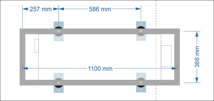
In this scenario, the rubber feet will have to be positioned further away from the corners (either close to or exactly where the condenser mounting points would be) because the solid concrete ends at the dotted line and I can't place the stand any further to the left:

LG_U24_Stand_-_Mounting_Top_Alt_rlrhay.jpg


But I have no idea how clever it is to use the rubber feet (regardless of which design I go with), both because of rubber degradation concerns (lifetime/need of replacement down the road) and reduced stability (as opposed to securing the stand directly to the concrete).
 
Status
Not open for further replies.

Part and Inventory Search

Sponsor