Enable
Structural
- Jan 15, 2021
- 793
I have an interesting one to look at. Existing three story building corner where steel lintels that pickup the brick façade, CMU backup wall, and OWSJ + floor loads from the interior (and roof) have corroded about 50% of the way through at the connection. As far as I am aware shoring is in-place and the intent now is to figure a way to repair the connection. As an FYI I'm not the EOR on this project. I am the sub-trade who is gently trying to push people in the right direction.
No existing DWGs available. Age unknown but not terribly old. Perhaps 70s construction.
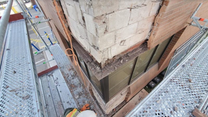
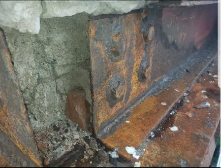
Detail is a bit funky. It appears like the corroded beams are supported via block on one side, and on the other, they are picked up by a bolted T-section. The T-section is cantilevered off a nearby HSS column on the inside.
There are multiple of these connections to be repaired.
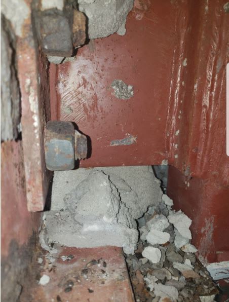
The original flange was cut-out at the connection during construction, which we suspect was done because the T-section interfered with it. As well, the holes are vertically slotted (read: torched on-site). I do not think this was the original intent because A) slotted holes were definitely site adds and B) the edge distance at some of these bolts is way below min code. Looks like it was hacked in-place to fit and not picked up during review.
The EOR has proposed a simple plate detail, which is rather wanting. Can't perform the specified welds (no field access) and they have us welding into corroded base metal. Doesn't deal with edge distance issues. Doesn't deal with the fact that the flange is missing at the most critical shear area.
I'm going to propose my own detail but wanted to run it by this crowd to see if I have missed anything. This is a rather unique situation that I have not previously come across.
Here is my intent:
A) I want to restore (in some way) the cut out flange for shear concerns
B) I want to add plate/steel area vertically to make sure bolts have min edge distances
C) I do not want to rely on the corroded metal and therefore want to design a repair that extends back further along the beam
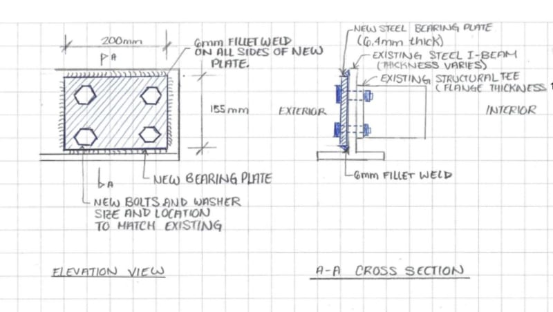
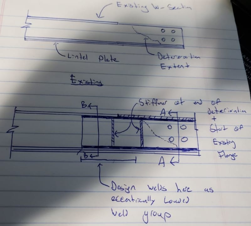
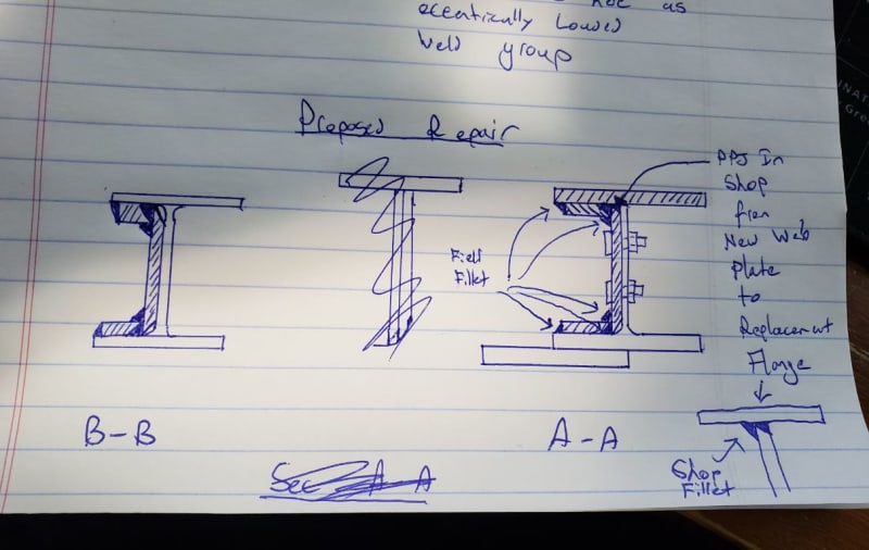
To accomplish this I am proposing to weld a doubler plate that extends beyond the corroded area and is designed as an eccentric weld group. I want to stiffen the "cantilevered" part of the doubler with plates top and bottom to form a "C-channel" shape extending to good material. This should restore the shear capacity of the section. Stiffeners are thrown in to help load transfer back to the web (prime welds on the doubler are to flanges). The edges of the plates forming the top and bottom flange of my new "c-channel" shape to be on an angle to by-pass fillet welds to doubler plate. Same goes for doubler plate edges at radius of beam-web connection.
I'll compute the weakest link in the T-flange connection (I suspect it's the weld to the plate welded to the HSS) and design for that load. No loads provided by EOR and on restoration projects I almost never get them.
Here is a little schematic of what I am thinking. Have I missed anything obvious?
No existing DWGs available. Age unknown but not terribly old. Perhaps 70s construction.
Detail is a bit funky. It appears like the corroded beams are supported via block on one side, and on the other, they are picked up by a bolted T-section. The T-section is cantilevered off a nearby HSS column on the inside.
There are multiple of these connections to be repaired.
The original flange was cut-out at the connection during construction, which we suspect was done because the T-section interfered with it. As well, the holes are vertically slotted (read: torched on-site). I do not think this was the original intent because A) slotted holes were definitely site adds and B) the edge distance at some of these bolts is way below min code. Looks like it was hacked in-place to fit and not picked up during review.
The EOR has proposed a simple plate detail, which is rather wanting. Can't perform the specified welds (no field access) and they have us welding into corroded base metal. Doesn't deal with edge distance issues. Doesn't deal with the fact that the flange is missing at the most critical shear area.
I'm going to propose my own detail but wanted to run it by this crowd to see if I have missed anything. This is a rather unique situation that I have not previously come across.
Here is my intent:
A) I want to restore (in some way) the cut out flange for shear concerns
B) I want to add plate/steel area vertically to make sure bolts have min edge distances
C) I do not want to rely on the corroded metal and therefore want to design a repair that extends back further along the beam
To accomplish this I am proposing to weld a doubler plate that extends beyond the corroded area and is designed as an eccentric weld group. I want to stiffen the "cantilevered" part of the doubler with plates top and bottom to form a "C-channel" shape extending to good material. This should restore the shear capacity of the section. Stiffeners are thrown in to help load transfer back to the web (prime welds on the doubler are to flanges). The edges of the plates forming the top and bottom flange of my new "c-channel" shape to be on an angle to by-pass fillet welds to doubler plate. Same goes for doubler plate edges at radius of beam-web connection.
I'll compute the weakest link in the T-flange connection (I suspect it's the weld to the plate welded to the HSS) and design for that load. No loads provided by EOR and on restoration projects I almost never get them.
Here is a little schematic of what I am thinking. Have I missed anything obvious?