Continue to Site

Eng-Tips is the largest engineering community on the Internet

Intelligent Work Forums for Engineering Professionals

  • Congratulations waross on being selected by the Eng-Tips community for having the most helpful posts in the forums last week. Way to Go!

Structural Theory Question Regarding Fixed/Pinned Ends

Status
Not open for further replies.

AThor

Civil/Environmental
Mar 8, 2017
34
US
Hello, I would like to get some responses about a theoretical question I have been wrestling with on numerous occasions. I think understanding the underlying concepts better would help clarify a lot of things in my head. I've attached an illustration of two recent problems that relate. Case 1 is a pipeline with bolted (in a ring pattern) flanges connecting segments of pipe, subjected to a transverse load. Case 2 is a single steel shape welded all around at each end to adjoining or supporting structure.

My question is regarding the end fixity of connections like this, but I wanted to ask it from a little bit different angle, focusing more on the forces or failure of the connection as opposed to the members. I know this is a common topic of question, and I get the general idea that every connection is somewhere between truly fixed and truly pinned. Every connection allows some degree of rotation, and every connection provides some degree of resistance to that rotation.

In case 1 of my examples, if you assume the flanges are fixed connections, the whole length becomes a single span, and the middle pipe will see greater bending stress. If you assume the flanges are pinned, then each individual span will bend, and the bending stress will be smaller. Let's say the pipe can withstand the bending stress whether the flanges are assumed fixed or pinned. But also, let's assume the flange would fail in bending if subjected to the moment they would see if fully fixed. Ideally, we would like the flanges to act as pins, allowing rotation and reducing stress in the pipes. But, for the flanges to allow rotation, there would be some degree of bending in the plate, right? So essentially the flanges have to start failing to relieve stress in the pipe?

For case 2, when looking at stress in the angle, it is more conservative to assume the welds at the ends are pins, not fixed. Let's say the angle is strong enough either way. But let's assume the weld isn't strong enough to transfer the full fixed end moment. Will the weld fail, even though this beam would be strong enough to support a simply supported condition?

To summarize my question, when you have partially restrained connections that are part of a structure with enough redundancy and strength (outside of the connections) to be stable and strong whether the connections are assumed pinned or fixed, but you have connections that would fail if subjected to the moment they would take if they're assumed fixed, do the connections actually fail, or does that moment redistribute somehow before any yielding happens in connection elements?

Hopefully I'm making a little sense here at least. I appreciate any discussion on the topic, and especially any reference texts or papers that discuss this topic that I can go read further on. Like I said, I feel like understanding what's going on here would be a lightbulb moment for a few different things in my head. Thanks!
 
 https://files.engineering.com/getfile.aspx?folder=821e2cfe-7ee4-42cc-b417-2d2e2fcc32c3&file=Fixity_Illustrations.pdf
Replies continue below

Recommended for you

AThor said:
In case 1 of my examples, if you assume the flanges are fixed connections, the whole length becomes a single span, and the middle pipe will see greater bending stress. If you assume the flanges are pinned, then each individual span will bend, and the bending stress will be smaller. Let's say the pipe can withstand the bending stress whether the flanges are assumed fixed or pinned. But also, let's assume the flange would fail in bending if subjected to the moment they would see if fully fixed. Ideally, we would like the flanges to act as pins, allowing rotation and reducing stress in the pipes. But, for the flanges to allow rotation, there would be some degree of bending in the plate, right? So essentially the flanges have to start failing to relieve stress in the pipe?
That was hard to decipher.

The whole length IS a single span between the supports not matter whether the connections are treated as pinned or fixed. But if you are considering internal connections as pinned then you have a catenary structure, that isn't something you want. For a pipe structure as drawn you should treat all connections as FIXED including the ends, these aren't simply supported. This will result in lower loads on your pipe but potentially moment on the support depending on the end detailing.

AThor said:
To summarize my question, when you have partially restrained connections that are part of a structure with enough redundancy and strength (outside of the connections) to be stable and strong whether the connections are assumed pinned or fixed, but you have connections that would fail if subjected to the moment they would take if they're assumed fixed, do the connections actually fail, or does that moment redistribute somehow before any yielding happens in connection elements?
Depends on the circumstances. In some cases it all roughly works out. In other cases designing an inflexible connection will lead to connection failure, there is a reason why structural bearings are a thing.
 
Thanks for trying to decipher my post. You are right, the pipe case would be a catenary if the connections are assumed hinges. The real world situation I was getting that example from is a floating debris boom with HDPE pipe, so we actually do want a catenary. It turns out that as the total span gets very large, it will behave nearly as a catenary even if the connections are assumed fixed. So, maybe that was not the best example to use.

human909 said:
Depends on the circumstances. In some cases it all roughly works out. In other cases designing an inflexible connection will lead to connection failure, there is a reason why structural bearings are a thing.

Can you elaborate a bit? When you say it depends, I'm guessing it depends on the relative stiffness of the connection and surrounding structure, among other things. For my second example of a single member with all around welds at each end, if the weld is connected to an infinitely rigid structure, is it correct to assume the welds need to be strong enough to resist the full fixed end moment or else they would fracture? Even though this member would work as a simply supported member?
 
connections are not special. the structure is designed the carry the loads applied. It would prudent (possibly an abundance of caution) to design to the worst possible case ... pinned ends produce the highest moment in the span, fixed ends produce the highest moment at the ends (and so critical for the connections). We call that "overlapping assumptions".

another day in paradise, or is paradise one day closer ?
 
Thanks. Enveloping the design for worst case assumptions certainly makes sense and seems like a good approach in a lot of situations. I'm just trying to better understand what's truly going on, both for situations where I am analyzing something existing versus designing something new, and to be able to better optimize new designs.
 
forget "truth" ... we'll never understand the "true" situation, except in very simple applications.

the path to structural failure has many twists and turns ... we start with some (any ?) fixity assumption, then local yielding/softening of the loadpaths redistributes loads and so on untill eventually the thing fails. Our analysis is based on (hopefully) conservative assumptions, and tests.

another day in paradise, or is paradise one day closer ?
 
Case 1

1. All flanges fixed

If the end flanges connect to something with stiffness, there will be continuity at each end, therefore a negative moment. If they are connected to a blind flange, the span is a simple span with zero end moments. To behave as a beam, one end support needs to be a roller, preventing axial force in the pipe. In that case the moment at internal flanges can be calculated using the expression for a simple beam. If both end supports are true pins, catenary action will occur in combination with pipe bending.

2. All flanges pinned.

Each pipe section develops bending stress as a simple beam spanning between flanges in addition to axial tension between end flange plates. The moment is zero at every flange.

Case 2

If the weld is not strong enough to develop end moments, the weld on the horizontal leg would start unzipping at the point of maximum tensile stress. This would continue across the leg but would likely stop at or near the vertical leg, at which point the angle would be acting as a simple beam with zero end moments.

BA
 
AThor said:
........do the connections actually fail, or does that moment redistribute somehow before any yielding happens in connection elements?

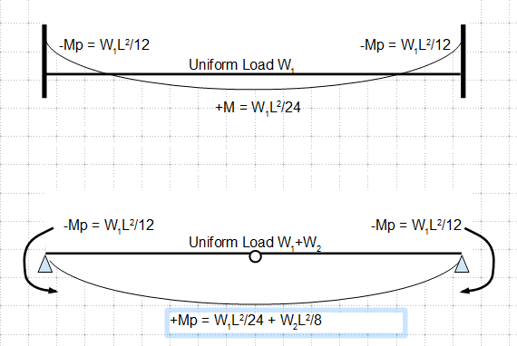
Here is my little contribution to your ending concern - the sketch shows a fixed end beam with an uniformly distributed load W1. A hinge is formed at each of the supports, as the connection was designed to plasticize at the maximum theoretical moment W1L2/12. Now the beam is further loaded with an additional uniform load W2, and soon the beam reached its design capacity Mp = W1L2/24 + W2L2/8, a hinge is thus formed. With 3 hinges in the system, the beam is said to be in a mechanism, that can no longer carry any additional load, in a sense, the beam has failed. Hope this helps.

image_myxysk.png
 
Thanks for each of your contributions. The points I quoted below help make it clearer. My next question was going to be, "is it common, or acceptable, for parts of a connection to go plastic, assuming the beam design only needs a simply supported end?". I did a quick google search and found this article: and the quote "Unlike many of the other types of connections, shear tabs rely on inelastic deformation to achieve the rotation capacity of simple shear connections..." So, in the case of shear tabs, the connected beam is designed for a pinned end, but the shear tab restricts some rotation, to the point where small parts of it may yield, allowing further rotation. But, it would be important to know that the parts of the connection that are yielding don't cause a reduction in the shear capacity of the connection, right? You wouldn't have to think about this too much when using common or prequalified connections, but if using more arbitrary connections, like my angle weld in Case 2, you would have to reduce the shear capacity of the connection by the length of the leg that would "unzip", if your analysis shows it will unzip under the FEM.

I'm probably overthinking this, but talking through it is very helpful.

rb1957 said:
...then local yielding/softening of the loadpaths redistributes loads and so on until eventually the thing fails...

BAretired said:
If the weld is not strong enough to develop end moments, the weld on the horizontal leg would start unzipping at the point of maximum tensile stress. This would continue across the leg but would likely stop at or near the vertical leg, at which point the angle would be acting as a simple beam with zero end moments.

r13 said:
A hinge is formed at each of the supports, as the connection was designed to plasticize at the maximum theoretical moment W1L2/12. Now the beam is further loaded with an additional uniform load W2, and soon the beam reached its design capacity...
 
AThor said:
My next question was going to be, "is it common, or acceptable, for parts of a connection to go plastic, assuming the beam design only needs a simply supported end?".

That would be both common and acceptable.

BA
 
Case 1- in cases like this, it is conservative for bending in the pipe to assume the ends are pinned, and conservative for bending in the end flanges and in the supports to assume that ends are fixed. In some references, they'll assume "partial fixity" for similar cases, which, in case you do a lot of extra testing or analysis, is just going to be an assumed number anyway. So unless you can come up with some way to justify the rigidity (or lack thereof) of the supports on the end, I would design the pipe assuming pinned and design the end flanges assuming fixed, and assume actual stress is somewhere in between.

One way this comes back to bite us in the vessel/tank industry is that occasionally piping people will assume a vessel or tank flange is "fixed" when in fact it may have considerable flexibility (and may also rotate with an applied axial load, or move longitudinally with an applied moment, or move independently of the load due to tank/vessel pressure and temperature changes). Anyway, they may come back with huge moments calculated on this basis, which it is unreasonable for the tank/vessel to support. So the approach above is not fool-proof.

Not shown there, and may not be significant, but a long unsupported pipe can vibrate in the wind even if structurally stable otherwise.

In case 2, I would neglect the end welds. You don't show a scale here, but the problem with this type of assembly is that with typical angle sizes, you can double the thickness of the angle cheaper than you can spend an extra 10 minutes proving you don't need to. So if it's extra critical or you're making a 1,000 of them or your wages are $2 a day or something, it may be worthwhile to spend some time on it, otherwise, simplify the analysis, make it stout, and move on.


"is it common, or acceptable, for parts of a connection to go plastic, assuming the beam design only needs a simply supported end?".

I would say it is acceptable, provides you have a handle on which part will fail in ductile manner rather than brittle, and that's why the code specifies different strength adjustment (reduction) factors to safe guard the designs for parts with different structural behaviors/failure mechanism.
 
Status
Not open for further replies.

Part and Inventory Search

Sponsor

Top