Continue to Site

Eng-Tips is the largest engineering community on the Internet

Intelligent Work Forums for Engineering Professionals

  • Congratulations waross on being selected by the Eng-Tips community for having the most helpful posts in the forums last week. Way to Go!

Structure Design Using Slope-Deflection Equations and Matlab 1

Status
Not open for further replies.

Tygra_1983

Student
Oct 8, 2021
116
Hi there, I was wondering if someone could help me.

I am designing a simple structure. I have attached a diagram and I am using the slope-deflection equations and using Matlab. Unfortunately I am getting strange results that I think are wrong. For the rotations at the joints I am getting zero which cannot be correct.

Here is my Matlab code:

clear
clc

% data

E = 2e+08;
I = 0.002;
EI = E.*I;
L1 = 5;
L2 = sqrt(5.^2 + 5.^2);
q = 100;
FEM1 = q.*L1.^2./12;
FEM2 = -FEM1;

% Symbolic mathematics

syms X1 X2 X3 X4 X5 X6 X7 X8 X9 X10

X1 = 0; X3 = 0; X5 = 0; X7 = 0;
X2 = -X8;
X4 = -X6;
X9 = -X10;

M1i = 4.*EI./L1.*X1 + 2.*EI./L1.*X2;
M1j = 2.*EI./L1.*X1 + 4.*EI./L1.*X2;

M2i = 4.*EI./L1.*X3 + 2.*EI./L1.*X4;
M2j = 2.*EI./L1.*X3 + 4.*EI./L1.*X4;

M3i = 4.*EI./L1.*X5 + 2.*EI./L1.*X6;
M3j = 2.*EI./L1.*X5 + 4.*EI./L1.*X6;

M4i = 4.*EI./L1.*X7 + 2.*EI./L1.*X8;
M4j = 2.*EI./L1.*X7 + 4.*EI./L1.*X8;

M5i = 4.*EI./L1.*X2 + 2.*EI./L1.*X4;
M5j = 2.*EI./L1.*X2 + 4.*EI./L1.*X4;

M6i = 4.*EI./L1.*X4 + 2.*EI./L1.*X6;
M6j = 2.*EI./L1.*X4 + 4.*EI./L1.*X6;

M7i = 4.*EI./L1.*X6 + 2.*EI./L1.*X8;
M7j = 2.*EI./L1.*X6 + 4.*EI./L1.*X8;

M8i = 4.*EI./L2.*X2 + 2.*EI./L2.*X9;
M8j = 2.*EI./L2.*X2 + 4.*EI./L2.*X9;

M9i = 4.*EI./L1.*X9 + 2.*EI./L1.*X10 + FEM1;
M9j = 2.*EI./L1.*X9 + 4.*EI./L1.*X10 + FEM2;

M10i = 4.*EI./L2.*X10 + 2.*EI./L2.*X8;
M10j = 2.*EI./L2.*X10 + 4.*EI./L2.*X8;

M11i = 4.*EI./L1.*X4 + 2.*EI./L1.*X9;
M11j = 2.*EI./L1.*X4 + 4.*EI./L1.*X9;

M12i = 4.*EI./L1.*X6 + 2.*EI./L1.*X10;
M12j = 2.*EI./L1.*X6 + 4.*EI./L1.*X10;

% Solving

Joint2 = M1j + M5i + M8i == 0

Joint4 = M2j + M5j + M11i + M6i == 0

Joint6 = M3i + M6j + M12i + M7i == 0

Joint8 = M4j + M7j + M10j == 0

Joint9 = M8j + M11j + M9i == 0

Joint10 = M9j + M10i + M12j == 0

Answer1 = solve(Joint2,X6)
Answer2 = solve(Joint4,X6)
Answer3 = solve(Joint6,X6)
Answer4 = solve(Joint8,X6)

solve(Answer1, Answer2)

I am hoping someone here knows how to use Matlab and is familiar with slope=deflection equations that can help me.

Kind regards


 https://files.engineering.com/getfile.aspx?folder=c93b376a-7d55-4f18-b24c-46fe445a3efa&file=SDE.pdf
Replies continue below

Recommended for you

No, unfortunately, I am not getting zero for the sum of the moments about the joints, NicOKai: Dam! I think we are better off than we were though - @BAretired.
 
Sorry to hear that. I found x2, x4 and x9 to be as follows, but I used relative EI/L, not the actual values:
x2 -5.294935592
x4 -6.311284333
x9 49.47392592

For the typical member, I considered K = 2EI/L to be 1.0, but for member 8, K would be 0.70711

On that basis, I find the following moments:

M2-1 = 0 - 2*x2 = 10.6kN=m
M2-4 = 0 - 2*x2 - x4 = 16.9
M2-9 = 0 - 0.7071(-2*x2 - x9) = -27.4kN-m ------- Sum = 0 (check)

M4-2 = 0 - (2*x4 +x2) = 17.9
M4-3 = 0 - 2*x4 = 12.6
M4-6 = 0 - (2*x4 +x6) = -x4 = 6.3
M4-9 = 0 - (2*x4 +x9) = -36.85 ------- Sum = 0 (check)

M9-2 = 0 - 0.70711(2*x9 + x2) = -66.22
M9-4 = 0 - (2*x9 + x4) = -92.64
M9-10 = 208.33 - (2*x9 + x10) = 208.33 - x9 = 158.85kN-m ------- Sum = 0 (check)

The sum of moments at Joints 2, 4 and 9 is zero as expected.

BA
 
@Tygra,

I did not use your EI values, so had not noticed that your values seem a bit inconsistent. If actual rotations and deflections are required, the correct values are needed.

The following are the values you used:

E = 2e+08; a value of 200,000,000 (not the usual units); E for steel is normally taken as 200,000 MPa, which is the same as 200,000 N/mm[sup]2[/sup]
I = 0.002; that seems very small. It should be given in consistent units.
EI = E.*I;
L1 = 5; this term is in meters.
L2 = sqrt(5.^2 + 5.^2);
q = 100; this term is in kN/m
FEM1 = q.*L1.^2./12; this results in units of kN-m
FEM2 = -FEM1;
It is advisable to maintain a consistent set of units throughout all calculations. If you don't, you tend to get very strange results. As mentioned earlier, for this problem, relative stiffness values are all that is required.

BA
 
I changed the units to be consistent. Thanks for pointing that out BAretired. However, still getting wrong results. I appreciate your method BAretired, but I would really like to crack this the way I have originally set out. When this problem is solved I would like to move on to even bigger structures, as I think this would be good for my career as civil engineer. saying this I have no idea what the error is in this problem. I am confused because on smaller problems I am getting correct answers. For example, this:

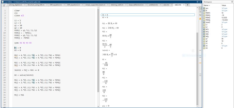
SDE_matlab_o0pzrx.png


As you can see this is correct
 
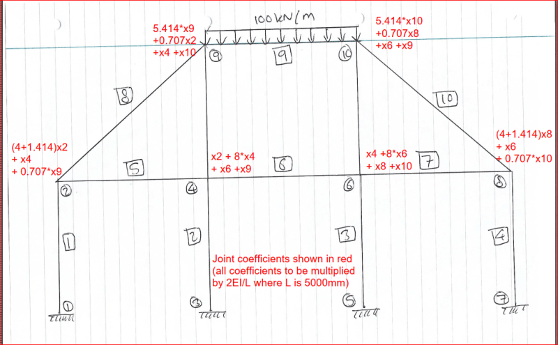
It appears to me that you have some errors in your joint equations. The sketch below shows the joint coefficients you should be using. They include the length difference for the diagonal members.

Capture_qmgzmj.png


@Tygra,

After writing the above, I was unable to find the inverse of the matrix. I don't know what is wrong.


Update: Found the inverse, but the answers can't be right because x2, x4 and x9 do not equal -x8, -x6 and -x10 respectively, which they must because of symmetry. Looks like we'll both have to sleep on it.

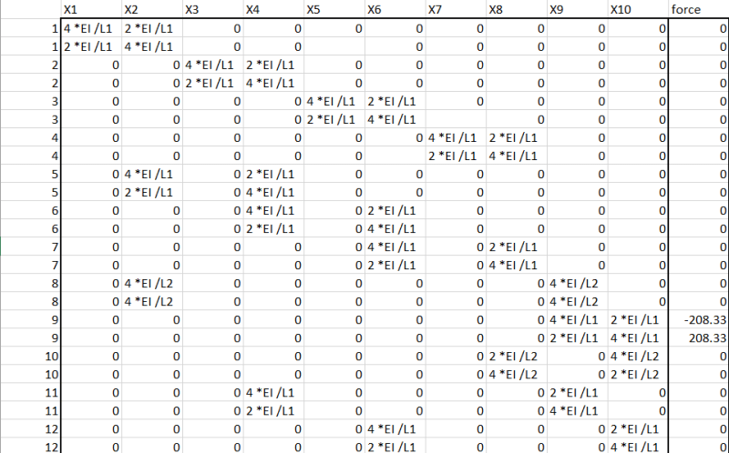
Update #2: Found the error. Made a mistake in typing one of the cells. The answers agree with the results I found using only three nodes.

Capture_zxp3ku.png


Rotations x2 through x10 are shown in column S of the table above. To get the correct rotation, multiply all values by 2EI/L.

BA
 
BAretrired, that is amazing what you have done. However, could your point out what error I made in my joint equations? This will be good for learning.
 
Tygra said:
BAretrired, that is amazing what you have done. However, could your point out what error I made in my joint equations? This will be good for learning.

I believe I was mistaken about an error in your joint equations. So far as I can see, they are all okay. I am attaching the results of both sets of calculations (see below). In both sets of results, the original joint matrix is from columns C to H. Fixed end moments are in column J. The inverse matrices are from columns L to Q and the final values of rotations are in column S.

In both cases, x2 = -x8; x4 = -x6 and x9 = -x10.

The sum of Joint moments is zero for both results below. If you are getting different results from those that I show, the problem may lie in a misunderstanding or misapplication of your software.

BA results on Rows 2 to 7:
Tygra results on Rows 9 to 14:

Capture_lghot5.png


Conclusion: there is nothing wrong with the equations in either set above. In both cases, the sum of moments at every joint is zero.

BA
 
I think it is a misunderstanding or a misapplication of my software (Matlab). However, I am not sure what route to go down though. I was thinking of making a matrix for X2,X4,X6,X8,X9,X10 values, but that is quite tedious. What do you think NicOkai?

Edit: just caught your edited post BAretired. Hoping you can save me from this torment tomorrow lol.

Edit2: I think we need someone that is exceptional in Matlab too.
 
Tygra,

So the way I described it is similar to how BAretired solved it.
stiffness_var_and_forces_kzqdox.png

FEM = [stiffness][rotation]
rotation = FEM\stiffness. I have attached the excel, sheet2 is the numerical expression. Try that and see if it works (kindly verify my units of E and I in the spreadsheet. Is this due tomorrow or it's a personal project? (I have an ideal but that we don't have time for that now, it involves writing a whole different script)

EDIT
If you break it down to Joint 2, Joint 4, Joint 6, Joint 8, Joint 9, and Joint 10 you should get the same matrix as BAretired.


Tygra said:
I think it is a misunderstanding or a misapplication of my software (Matlab)
I'd say you understand but misapplication. The script has been written in a fixed manner, meaning, you can't run it once to solve the problem. It is going to be tedious to make the matrix. To simplify things for yourself, do it like BAtired. Get you equations, go to excel or another matlab tab, run them and get the values and solve the inverse.

Tygra said:
When this problem is solved I would like to move on to even bigger structures, as I think this would be good for my career as civil engineer.
We did something similar using the stiffness matrix back in school but I can't share the script since I wasn't the only one who worked on it but I can share the idea later with you. I tried getting my friend to give me access to his MATLAB account since I no longer have the license but couldn't reach him. I'm planning to learn Python since it is free and try developing scripts for my designs as well.

I am really sorry I couldn't be of help at the moment. All I can say is BAretired got it correct in Excel.
 
Is this due tomorrow or it's a personal project?

In November there will be a coursework where we have to design a steel-framed building. The lecturer said we will need our knowledge from the previous modules of structural and stress analysis in year one and structural analysis in year 2. For this reason, I have been pratising with slope-defection equations that I learnt in structural analysis to prepare myself for the coursework. I might be wrong, but I think the structure for the coursework might be more complicated than the example we have been working on.

We did something similar using the stiffness matrix back in school but I can't share the script since I wasn't the only one who worked on it but I can share the idea later with you. I tried getting my friend to give me access to his MATLAB account since I no longer have the license but couldn't reach him. I'm planning to learn Python since it is free and try developing scripts for my designs as well.

I am really sorry I couldn't be of help at the moment. All I can say is BAretired got it correct in Excel.

That is absolutely fine. I thank you and BAretired for your patience and all your help thus far. I have decided to adopt your method, but I thought I would have a go at solving a smaller structure. However, I am not getting the correct rotations. Could you check my workings to see where I have gone wrong, NicOkai?

Here is the structure with its answers.
[URL unfurl="true"]https://res.cloudinary.com/engineering-com/image/upload/v1634570812/tips/Stiffness_method_wilfbz.pdf[/url]

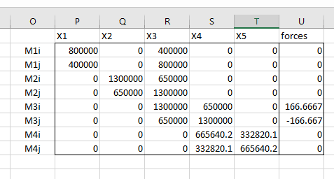
This is my Excel matrix

matrix_sde_hxk3ki.png


This is the Matlab code with the rotations I am getting using.

A = [800000 0 400000 0 0
400000 0 800000 0 0
0 1300000 650000 0 0
0 650000 1300000 0 0
0 0 1300000 650000 0
0 0 650000 1300000 0
0 0 0 665640.2355 332820.1177
0 0 0 332820.1177 665640.2355]


B = [0
0
0
0
166.6666667
-166.6666667
0
0
]

Y = pinv(A)*B


1.0e-03 *

-0.0779
-0.0779
0.0974
-0.1180
0.0944
 
Hint:

You have to solve two equations, one for Joint 3 and one for Joint 4. The other joints are all fixed.

BA
 
BAretired said:
You have to solve two equations, one for Joint 3 and one for Joint 4. The other joints are all fixed.

Only Joint 3 and 4 can rotate. Also I think MATLAB "pinv" gives "different" solution" as it's a pseudo inverse. Try using "pinv", "inv" and "/" to solve an inverse of matrix you know the solution and watch the results you get.
 
Still getting Incorrect results guys.

m1i = 0.8e+6, m1j = m1i./2
m2i = 1.3e+6, m2j = m2i./2
m4i = (2e+8.*0.006)./sqrt(4.^2+6.^2), m4j = m4i./2
FEM1 = 166.667
FEM2 = -166.667

syms X1 X2 X3 X4 X5

X1 = 0; X2 = 0; X5 = 0


M1i = m1i.*X1 + m1j.*X3
M1j = m1j.*X1 + m1i.*X3

M2i = m2i.*X2 + m2j.*X3
M2j = m2j.*X2 + m2i.*X3

M3i = vpa(m2i.*X3 + m2j.*X4 + FEM1,5)
M3j = vpa(m2j.*X3 + m2i.*X4 + FEM2,5)

M4i = vpa(m4i.*X4 + m4j.*X5,5)
M4j = vpa(m4j.*X4 + m4i.*X5,5)

joint3 = vpa(M1j + M2j + M3i,5)
Joint4 = vpa(M3j + M4i,5)


y1 = equationsToMatrix(joint3)
y2 = equationsToMatrix(Joint4)

A = [y1; y2]
B = [FEM1; FEM2]

Theta = inv(A)*B

X3 = Theta(1) = 0.000077298482151272739116422631226081
X4 = Theta(2) = 0.00014791975279127278677572495087085


3.4e+6.*X3 + 650000.*X4 + 166.67 = 333.33700000000000159161572810262
 
I'm not sure how you arrived at those values for X3 and X4, but my calcs are shown below. I have used relative stiffness values instead of the actual values, because all those zeros tend to confuse me, so the rotations are not identical to those shown in Answers, item (c), in fact, they differ by a factor of 10^6.

Column 1:
4EI/L = 0.8*10^6;​
k1 = 0.8​
Beam 2, 3:
4EI/L = 1.3*10^6;​
k2 = k3 = 1.3​
Beam 4:
4EI/L = 2*10^8*0.006/5 = 665,640​
k4 = 0.6656​

Slope-deflection equations
Fixed end moment = 125(4^2)/12 = 166.67kN-m

Joint 3: θ3(k1+k2+k3) + θ4(k3/2) = 166.67
(0.8+1.3+1.3)θ3 + (1.3/2)θ4 = 166.67​
θ3*3.4 + θ4*0.65 = 166.67-----------------------(1)
Joint 4: θ3(k3/2) + θ4(k3+k4) = -166.67
θ3*0.65 + θ4*1.9656 = -166.67------------------(2)​
(2) times (3.4/0.65)
θ3*3.40 + θ4*10.282= -871.81------------------(3)​
(1) minus (3)
-9.632θ4 = 1038.48;
θ4 = -107.82
From Equation (1),
θ3 = [166.67 - (-107.82*0.65)]/3.40 = 69.63

BA
 
For the last parts to the question, see below:

Question (d)
Moment in Beam 2 is -0.65*θ3 = -45.26kN-m and -1.3*θ3 = -90.52kN-m left and right respectively.

Question (e)
member 3: Msimple = wl^2/8 = 250kN-m
m3 left = 166.67 - k3(θ3 + θ4/2) = 146.23
m3 right = -166.67 - k3(θ3/2 + θ4) = -71.76
m3 midspan = 250 - (141.0 + 94.90)/2 = 141.0kN-m

BA
 
@Tygra,

How about an update? Was any of the above helpful?

BA
 
Hi BAretired,

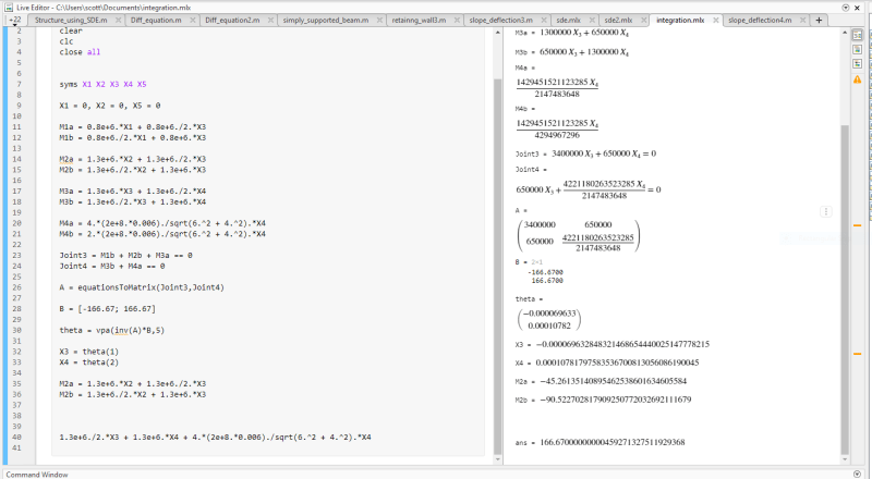
Yes, I have solved both problems now, although the smaller problem does have me scratching my head a bit. This is because I have attained the answers that in the handout (the yellow sheet I previously attached), but strangely my joint equations doesn't equal zero. See the image below:

results_e1vifi.png


For the larger problem my joint equations don't equal zero exactly, but they are a very small number close to zero - like 7.3e-39. Do you think this could well be the correct answers? The rotations match the symmetrical geometry of the structure too.
 
Sounds good to me! 7.9e-39 is about as close to zero as you will get with a computer. Congratulations!

BA
 
Thanks, BAretired. We got there in the end! I have found a great function in Matlab called 'equationsToMatrix' that converts the linear equations into matrix form. Solving the matric gave me the correct answers!

What do you think about the smaller problem? I am getting the correct rotations of X3 = -6.96e+5 and X4 = 1.08e+4, but my joint equation equals 166.67?
 
Status
Not open for further replies.

Part and Inventory Search

Sponsor