Continue to Site

Eng-Tips is the largest engineering community on the Internet

Intelligent Work Forums for Engineering Professionals

  • Congratulations SDETERS on being selected by the Eng-Tips community for having the most helpful posts in the forums last week. Way to Go!

Structure in elastic field

Boby2

Student
Apr 3, 2025
5
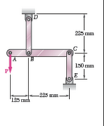
Connection BD is made of brass (E = 105 GPa) and has a cross-section of 256 mm^2. Connection CE is made of aluminum(E = 73 GPa) and has a cross-section of 320 mm^2.
• Determine the maximum force P that can be applied vertically at point A if the displacement of A must not exceed 0.35 mm.
- Suppose that element AC is rigid.

I thought of writing the relations between the tension on each connection BD and CE and then imposing that the elongation of the two is equal. Then since BD therefore lengthens the tie rod and CE therefore shortens the strut, imposing that the algebraic sum of the two forces is equal to P.
 

Attachments

  • Screenshot 2025-04-03 alle 13.24.07.png
    Screenshot 2025-04-03 alle 13.24.07.png
    71 KB · Views: 8
Replies continue below

Recommended for you

post student posts in the student forum. Solve ABC as a free body. Both CE and BD are in tension. Apply a unit load (100N) at A, calculate the deflection at C and B and therefore the deflection at A. How does this compare to your limit (0.35 mm) ? what factor to apply to your unit load to get your limit ?
 
ok sorry for posting in this forum.
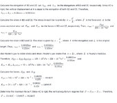
My solution is:

The only doubt is that the CE connection is a strut so in compression in the balance must a negative sign be put?
 

Attachments

  • IMG_0260.jpg
    IMG_0260.jpg
    852.8 KB · Views: 9
The bar AC does not remain horizontal so the deflections are all not equal to each other.

If CE is rigid, what is the deflection at A due to elongation of BD?
If BD is rigid, what is the deflection at A due to elongation of CE?

The total deflection at A is the sum of those two deflections.
 
CE is in tension ...
C will deflect up, B will deflect down ... A will deflect down.
 
CE is in tension ...
C will deflect up, B will deflect down ... A will deflect down.
The connection in B and C are hinges and that is why both DB and CE are in traction.
Then deltaA = DeltaBC +Delta CE=0.35mm
 
BD and CE and then imposing that the elongation of the two is equal. Then since BD therefore lengthens the tie rod and CE therefore shortens the strut, imposing that the algebraic sum of the two forces is equal to P.
Your approach totally wrong. Algebraic sum of P+ Fce= Fbd
Just apply equiblirium equations , find the tension forces Fbd and Fce in terms of P . ( Fbd=14P/9 and Fce=5P/9)
Then calculate the deflections of BD and CE . Check using linear ratios . Sum of them will control the 0.35 mm allowable deflection. If elongations Dbd and Dce, ( Dbd + Dce)=225*0.35/350=0.225 mm.
 
Last edited:
Your approach totally wrong. Algebraic sum of P+ Fce= Fbd
Just apply equiblirium equations , find the tension forces Fbd and Fce in terms of P . ( Fbd=14P/9 and Fce=5P/9)
Then calculate the deflections of BD and CE . Check using linear ratios . Sum of them will control the 0.35 mm allowable deflection. If elongations Dbd and Dce, ( Dbd + Dce)=225*0.35/350=0.225 mm.
The algebraic sum should not be: P+Fbd=Fce because Fbd is in compression directed downwards and Fce is in tension directed upwards.
 
BD is in tension pulling upwards from B. Nothing is in compression.

Fbd-P-Fce = 0; rearranged Fbd = P + Fce, which is what Hturkak wrote.

Fbd pulls up, P and Fce pull down on A-B-C.
 
BD is in tension pulling upwards from B. Nothing is in compression.

Fbd-P-Fce = 0; rearranged Fbd = P + Fce, which is what Hturkak wrote.

Fbd pulls up, P and Fce pull down on A-B-C.
Ok thank you so much.
 
"Then deltaA = DeltaBC +Delta CE=0.35mm" ... this is just sooo wrong.

You can solve the problem two ways ...

1) "unit load" ... apply a unit load, 100N; determine deflection at B and C; determine the deflection at A; then scale your unit load to make this 0.35mm (multiply the unit load, 100N, by 0.35/dA.

2) solve it algebraically. for a variable P determine the deflection at B and C, and then determine the deflection at A, then solve for P.

I suggest you review Free Body Diagrams ... they are absolutely fundamental to structural analysis.

I was going to suggest a bonus question (what happens if we make ABC non-rigid ?) but I think you are struggling with the basic question.
 

Part and Inventory Search

Sponsor