Continue to Site

Eng-Tips is the largest engineering community on the Internet

Intelligent Work Forums for Engineering Professionals

  • Congratulations 3DDave on being selected by the Eng-Tips community for having the most helpful posts in the forums last week. Way to Go!

Strut & tie pile caps

Status
Not open for further replies.

MIStructE_IRE

Structural
Sep 23, 2018
816
The other strut and tie thread has got me thinking..

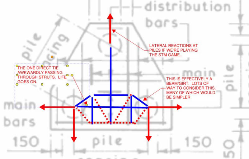
We normally use the strut and tie analogy for pile cap design. This load path is easily followed for 2 or 4 pile caps.

However, for a triple pile cap the same analogy is often used. But the reinforcement is rarely placed parallel to the theoretical tie.

If the theoretical tension force is along the crudely marked up blue lines attached, how is the rebar in the X or Y direction considered as resisting this?

In reality it does some sort of flat slab FE distribution. But strut tie seems like a poor analogy for a triple cap if the bars dont follow the tie line - which they never do..

Any thoughts?
 
 https://files.engineering.com/getfile.aspx?folder=3c151a64-dbca-43bc-a78d-8e51c4f93743&file=4E1C38EA-6416-4138-B30F-AF8744603DDF.jpeg
Replies continue below

Recommended for you

Well, I wouldn't say the bars never follow the tie line. I've heard of triangular caps with rebar laid out in a triangular fashion, and designed one myself (though it was never built, for other reasons).

But if you have perpendicular bars, as long as the geometry works out to provide the requisite area of steel in the direction needed, and within a reasonable tie width... why not?

----
just call me Lo.
 
There's some decent discussion here that may interest you: Link

With regard to juxtaposing STM methodology with orthogonal bar layout:

1) I note that the CRSI manual, which is kind of the well spring for pile cap information in my market, does in fact imply a bar layout consistent with STM. See below.

2) Perhaps, if one is going orthogonal, STM should not be used in its conventional form. Sometimes the answer is just that easy. In that case, the model would seem to be load supported on a beam that itself is supported by a pile at one end and a girder at the other. I don't love this as I suspect it's a poor representation of real, two-way behavior.

3) I've made an attempt below to rationalize STM with an orthogonal layout. Only the bottom steel is being considered. Ugly but not impossible. I suspect that this is a pretty good representation of what actually occurs. In plane, the cap ought to be pretty stiff and strong even if no explicit attention has gone into making it so.

4) I've heard it argued that the vector sum of the contributions of the orthogonal bars can be treated as faux in-line bars. I worry that this often falls apart with respect to anchorage detailing etc. That said, that would be one benefit of the generous edge distances that you typically see with these things. If this is/was the intended rationale, though, I sure would like to see that in print someplace.

c01_vwbzvc.jpg


c02_nmlp2f.jpg
 
Yes, as I was writing it, I had that same thought about #4. Maybe we should be thankful for the looser tolerances for pile installation.

----
just call me Lo.
 
Status
Not open for further replies.

Part and Inventory Search

Sponsor