efFeb
Structural
- Dec 25, 2019
- 68
Good morning,
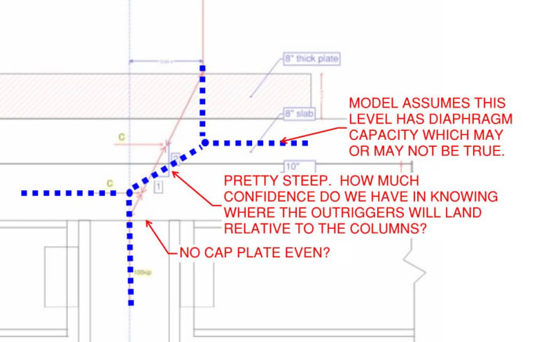
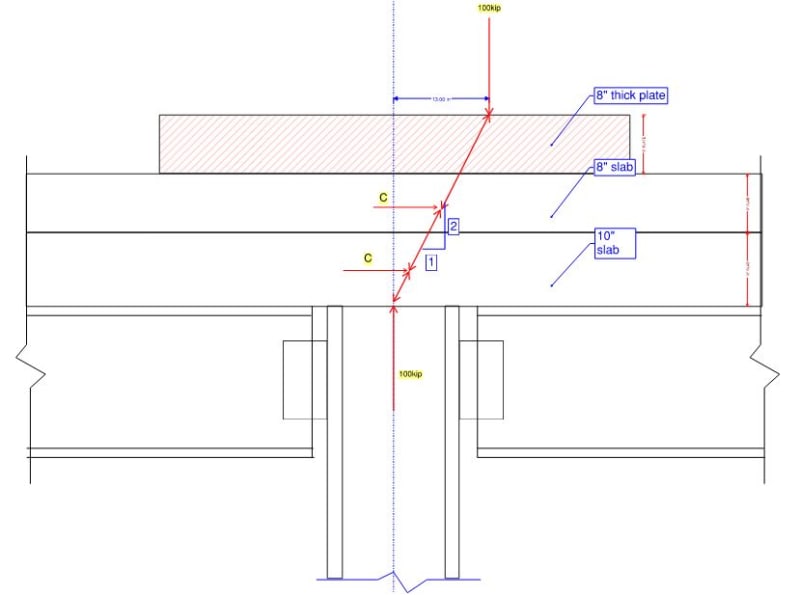
I am doing a check for some pretty heavy crane loads on an existing structure. I am finding that the columns are able to take the additional crane loads, but that the steel beam connections do not have enough capacity. The outriggers are situated close to the columns, but with offsets of around 1 ft from the column centroid.
The contractor has offered to bring in a very thick plate to sit beneath the outrigger pad, and I also have two layers of slab (10" slab and 8" slab sitting directly on top of each other, but not connected by dowels along the interface).
With all of this depth, I am wondering if a strut and tie model would be appropriate? I am not sure that I have my model correct, with the three layers and different materials, but have attached my sketch here. If anyone has done a similar check or has any input / thoughts, I would love to hear from you.
Thank you so much in advance,