Continue to Site

Eng-Tips is the largest engineering community on the Internet

Intelligent Work Forums for Engineering Professionals

  • Congratulations SDETERS on being selected by the Eng-Tips community for having the most helpful posts in the forums last week. Way to Go!

Strut strength with ligs? 1

Status
Not open for further replies.

dis_

Structural
Nov 19, 2020
17
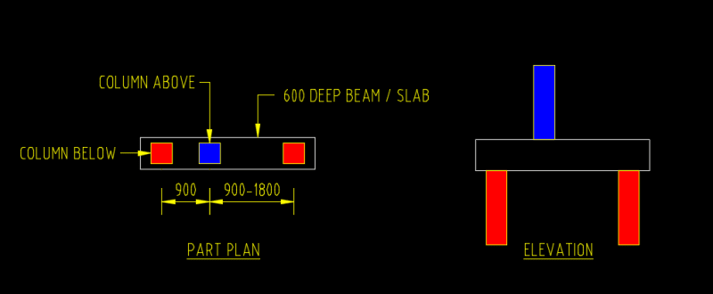
I have this offset column as shown below. The transfer point load from the column above is 1000kN.

I am at a point where I can design it using strut & tie or a normal beam as per AS3600 since strut angle is about 30 degree.

When I design it as strut tie, I find the strut strength fails while it passes easily with ligs if it is designed as a normally beam. The reason why STM fails is strut strength has been reduced a lot by efficiency factor beta_s and it doesn't consider the ligs contribution even if I add ligs in. The Code does allow me to consider the enhancement by the reinforcement, by which I can design the strut as column. But the reinforcement has to be parallel to the strut with ligs at a angle in this case as well, which is not practical.

My question is, if I provide normally vertical ligs, how much strength the strut will improve if I design it using STM since the strut has been confined in some way. Any thoughts?
stm_cblpz0.png
 
Replies continue below

Recommended for you

I also have this column transition issue that I think STM is applicable as well. But the strut strength just fail a bit. I believe providing vertical ligs will improve its strength but the Code doesn't cover this from what I know.

stm2_eiuieh.png
 
1) It's generally thought that a good strut and tie model is set up just as you have: with the simplest possible load path such that the minimum amount of strain is required to mobilize that load path. The trouble, as you've discovered, is that the shallow strut angle and the distregarding of the stirrups re shear capacity produce results that are worse than conventional, sectional design sometimes.

2) One approach that you might take, although I don't recommend it here, is to model your beam as smeared / distributed struts and ties, in opposition of #1. This will make use of your stirrups for shear, steepen your strut angles, and get you closer to that sectional design result.

3) The cost of #2 is that, in order to mobilize your assumed load path, you have to crack the heck out of your beam in shear. And that takes us back to #1 and the reasons why some codes insist that we use strut and tie instead of sectional methods when shear spans are low.

4) There are a number of approaches to the column situation and it is partially dependent on the story that you wish to tell there with respect to the maintenance of equilibrium at the joint. One common, low effort approach is to treat the overlapping area within the slab/beam as a short column in it's own right. Rebar, stirrups, etc as required. This often means that the upper and lower columns are designed to share the moment generated by the eccentricity within the joint rather than also sharing that moment with the adjacent slabs/beams which is yet another approach,
 
Thank you for your explanation.
When using STM, I believe the bursting check is taking care of the cracking. Shouldn't the strut strength be independent from this? ie shouldn't the strut strength be increased by the ligs even it is vertical.

If the overlapping area is very small, say 150mm x 200mm only. Does that mean we need to design the 150mm x 200mm to take the entire axial force from the upper column?
 
dis said:
When using STM, I believe the bursting check is taking care of the cracking. Shouldn't the strut strength be independent from this? ie shouldn't the strut strength be increased by the ligs even it is vertical.

1) The bursting check would take care of one kind of cracking: that associated with stresses perpendicular to the strut and, therefore, best resisted by reinforcement placed perpendicular to the strut. Potential shear cracking is, of course, a separate issue.

2) Reinforcement placed perpendicular to the strut confines the strut and, therefore, increases the strut's compressive capacity. So, in that sense at least, the reinforcement and the strength of the strut are very much interdependent.

3) Vertical reinforcement is likely to be less efficient at confining your struts than is reinforcement placed perpendicular to the struts per [#1]. More importantly, there are bursting stresses present that need to be resisted by reinforcement running across the thickness of the member. Normal beam shear reinforcement usually doesn't provide this other than at the extreme faces of the member.

dis said:
Does that mean we need to design the 150mm x 200mm to take the entire axial force from the upper column?

4) Yes, if and only if you use the method that I described in my previous post. There are other methods such as straight up strut & tie. Unless your slab is very thick, you may need some kind of localized slab thickening (beam, drop panel...) at the joint in order to make a strut and tie check pan out.
 
Thanks for your detailed explanation.

If I want to design it this way, how do I confine this overlapping area considering the area is so small that no enough vertical bars (<4) can be placed for the ligs? If I use the STM the inclined bars and ligs will not be practical and even if it is, how do I deal with the detailing such as splice? Looks like drop panel is the only option given that this offset column can not be avoided, but the architect will say no.
 
1) 150 mm x 200 mm may well be too small of an overlap for this stragegy. Draw it scale, run some numbers, and let your judgment be your guide.

2) I don't know that you actually need ties for the overlap with this. You might omit them altogether if the bars are stocky enough or get your confinement wiht U-bars etc.

3) In the absence of ties, maybe just stick two large diameter bars in there to get the job done.

4) I agree that inclined bars for the column joint strut will likely not be practical. The strategy that I proposed really has the over lap reinforcement as vertical dowels that terminate into the members above and below as non-contact, offset lap slplices. That may mean concentrated ties at the top of the low column and the bottom of the high column to deal with burstnig stresses there.

 
You're most welcome dis. Best of luck with your project.
 
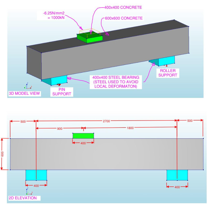
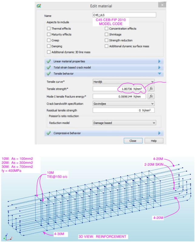
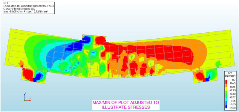
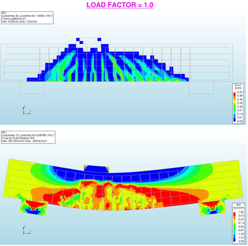
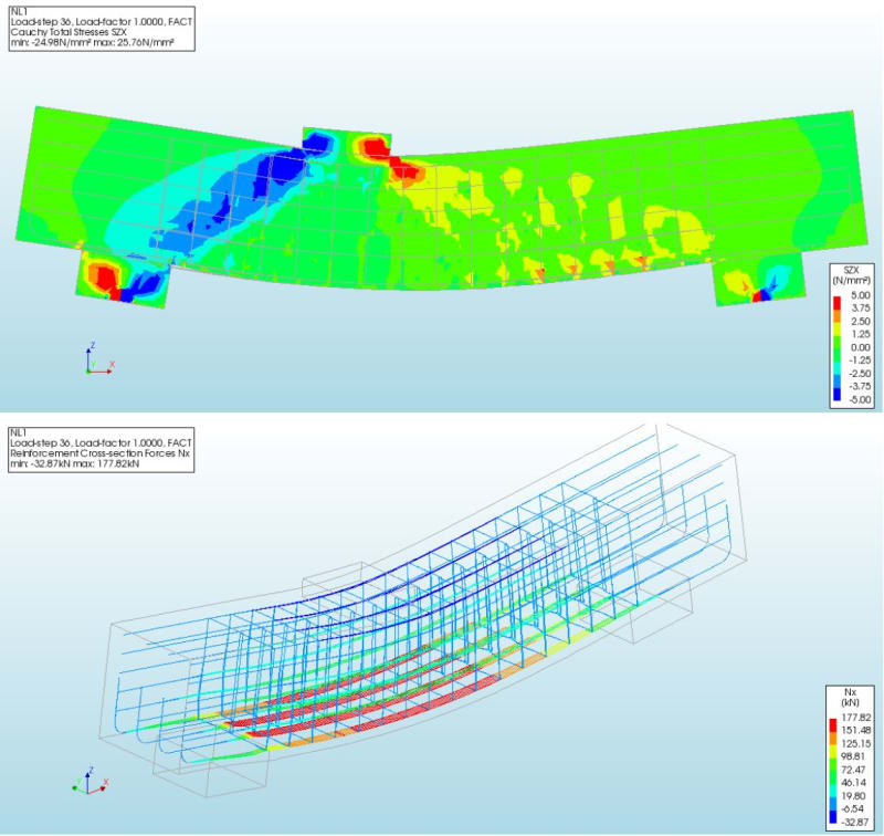
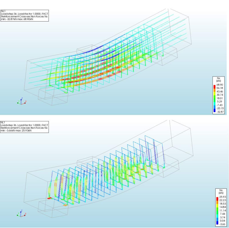
To help show the flow of the forces I mocked up a model based on some assumed dimensions and parameters. I don't mind re-running the analysis if you correct the dimensions. This problem has popped up a few times and I was interested. It is easy to include the rebar and additional parts being discussed if you include a sketch. I have been using this software for another project, so I used a C45 concrete material model from the CEB-FIP Model code 2010. That too can be changed easily.

Model dimensions used:
IMAGE-1_nvwobt.jpg


Concrete material properties and reinforcing:
IMAGE-2_u3wdpe.jpg


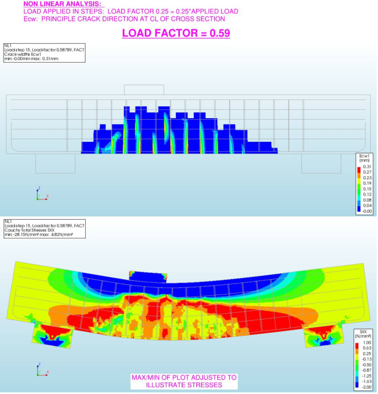
Load Factor = 0.59 Ecw and SXX
IMAGE-3_pm0w2w.jpg


Load Factor 0.59 SZX Stresses:
IMAGE-4_s8kmhn.jpg


Load Factor 1.0: Ecw and SXX
IMAGE-5_olcvap.jpg


Load Factor 1.0: SZX and Bottom Reinf Forces
IMAGE-6_ojwfvw.jpg


Load Factor 1.0: Mid Reinf and Tie forces
IMAGE-7_p0nmbn.jpg
 
Hi Brad805. Thank you for your help.
You model is one of the scenario I have. May I ask what program is this? I am impressed that it produces the tie forces as well.
 
Thank you. I will have a look
 
Status
Not open for further replies.

Part and Inventory Search

Sponsor