Continue to Site

Eng-Tips is the largest engineering community on the Internet

Intelligent Work Forums for Engineering Professionals

  • Congratulations KootK on being selected by the Eng-Tips community for having the most helpful posts in the forums last week. Way to Go!

Strut Tie Help

Status
Not open for further replies.

sauce_man

Structural
Apr 14, 2020
28
Hello again,

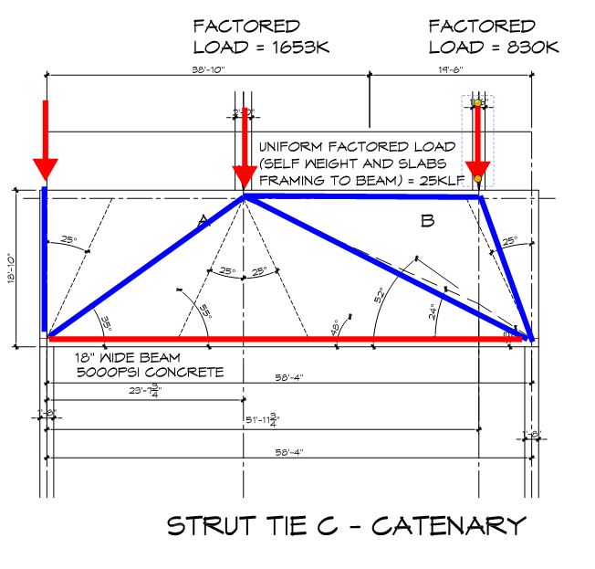
I think we have some experts on this thread so I really hope someone can help me. Please refer to the attached sketch.

I am having difficulty trying to design a deep beam. there are two transfer loads. one toward center span and one close to the beam end.

For my strut tie model A&B I am concerned because I have a theoretical tie below the point load, which also lies within 25deg from vertical (compression strut in a tie zone?)

For model C I am trying a catenary style layout, similar to "direct strut models" for symmetrically loaded deep beams like many examples. however one point is quite lower than the other and the struts are becoming shallow in their angle relative to horizontal. not sure if this is working.

for model D I am trying to simplify by saying tie the load near the support at the top and bring the strut down to the support. then treat the near-mid span load as a regular strut tie model. Again, does this make sense?

to note: supporting columns have already been poured and I believe i am having problems with the stresses at nodes and struts in general, what can i do besides increased the psi of the concrete?

I am not an expert on this subject matter so all advice is welcomed!!
 
 https://files.engineering.com/getfile.aspx?folder=13d0eda5-157c-403d-ab0b-27abbb51e025&file=Strut-Tie_Layouts.pdf
Replies continue below

Recommended for you

Also I am assuming I can apply the self weight of the system and line loads to the point loads based on their trib. Any thoughts?
 
Fun....

I favor your model C although I don't feel that there's anything "catenary" about it. I'd do a hybrid design wherein:

1) I'd assume the first model below, in general, even if the one strut is getting a bit shallow. In general, direct load paths will be stiff load paths and this model reflects my gut feel for how I suspect load will wind up being transferred.

2) For added safety, I'd assume the second model below for the sake of designing in the stirrups between the point loads.

sauce_man said:
Also I am assuming I can apply the self weight of the system and line loads to the point loads based on their trib. Any thoughts?

I believe that to be the normal practice when the self weight and uniform loading is relatively small in comparison to the point loads.

sauce_man said:
...what can i do besides increased the psi of the concrete?

1) Confine the struts and take numerical advantage of that if your code allows it.

2) Run rebar within your struts sort of like mini-columns. This isn't very constructible unfortunately.

3) Embed steel members within your beam. this is pretty drastic.

C01_nvgnyb.jpg
 
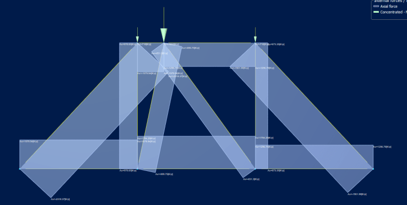
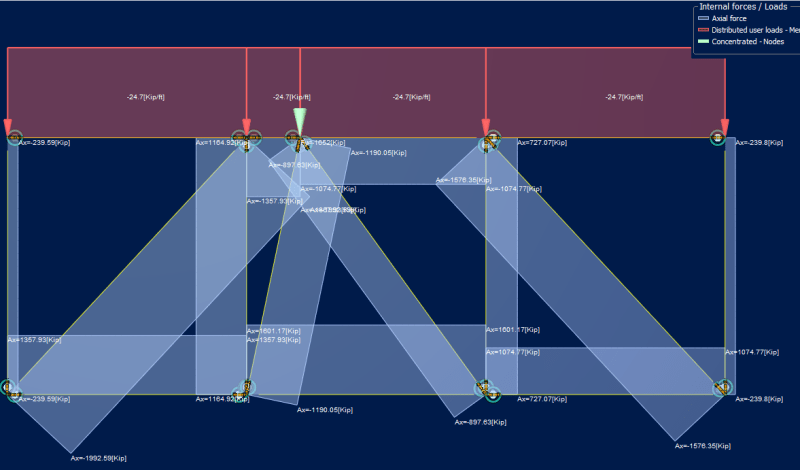
With the line load of 25 klf and span 58.33' that total is almost the same magnitude as the transfer load near mid span. I am wondering if it is justified to split the total into two point loads t 3rd points and add more struts. If i simply add it to the near mid span point load im coming up with humongous rebar demand, like 55 #10's grade 60 does that sound completely nuts? note the graphic below does not include right hand transfer load

2021-01-19_1_vgxaqj.png
2021-01-19_ek2q1t.png
 
OP said:
If i simply add it to the near mid span point load im coming up with humongous rebar demand

Yeah, I could see how that would be pretty conservative.

OP said:
I am wondering if it is justified to split the total into two point loads t 3rd points and add more struts.

Sounds reasonable. You gotta use your judgement with this stuff, generally ensuring that:

1) The centroid of your bullshit loads roughly matches the centroid of your real loads and;

2) At any section the shear and moment induced by your bullshit loads aren't miles off of the shear and moment induced by your real loads.

From an effort perspective, the trouble with introducing a bunch of new struts to smooth out the distributed loads is that it results in nodes that have more incoming members and are, therefore, more tedious and error prone to check.

If it were me, I don't think that I'd bother with anything more refined than the model shown below for uniform load modelling.

C01_mq2kax.jpg
 
Koot thanks for all the input!!

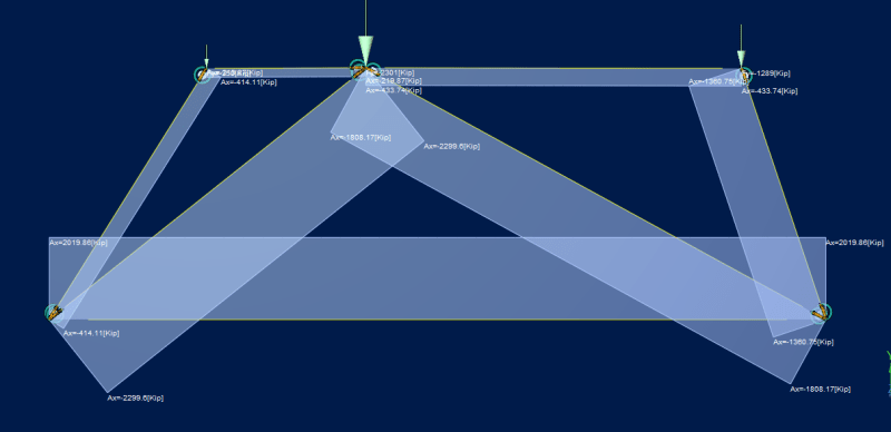
Finally, i think we will be adding the skewed left strut and break the uniform load into three pieces to better simulate moment and shear contributions from the uniform load. when added only to the transfer locations the tie force is just so high.

2021-01-19_2_stvhoe.png
 
Since it's iterative, I'd say use software to play around until you get what you want. It will also help you understand how it works.
CAST is free. Follow example as the link below:
Link

EDIT: I just saw that you are actualy - using software. Ignore my comment!
 
Status
Not open for further replies.

Part and Inventory Search

Sponsor