Continue to Site

Eng-Tips is the largest engineering community on the Internet

Intelligent Work Forums for Engineering Professionals

  • Congratulations KootK on being selected by the Eng-Tips community for having the most helpful posts in the forums last week. Way to Go!

Strut-tie-model Idealization for Girder-beam-joint of reinforced concrete

Status
Not open for further replies.

Baek

Civil/Environmental
Oct 19, 2015
14
Hello all,

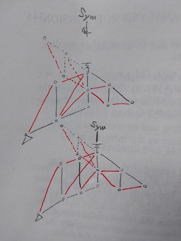
I have a sort of research to be done on strut and tie model related to reinforced concrete girder to beam joint which of monolithic cast. Here are described specimens, with a few necessary information for you to picture them. Overall test layout is simply shown below and #1, #2, and #3 are focused on showing strut and tie idealization and the only difference between specimens which is height of loading beam (BEAM). Circle is for node, black is for tension tie, red is for compression strut and dashed line is just for visual distinction of a part behind another part.
Longitudinal rebar is on the bottom of supporting beam (GIRDER) and on top of BEAM. GIRDER contains minimum stirrups with hanger reinforcement (11.2.12 of CSA A23.3-04, not required by ACI) and BEAM contains just one stirrup on each overhang, so two in a BEAM. No torsion should be induced since specimens and loads are symmetrical. Shear and bending are the only elements of external force occurring failure.
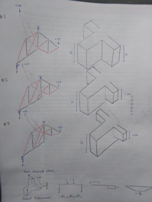
STM_Idealization_4_zh1uxa.jpg

Here are my questions.
1. Should I defer inclination angle of GIRDER between specimens #1, #2 and #3, since the angle in BEAM is different? (The angle should decrease as height decreases.)
2. Is there any better idealization of specimens especially drawn parts using 3D strut-tie-model?
3. Is there any better idealization of specimens especially drawn parts other than strut-tie-model?
4. Stiffness of spring should be about 400kN/15mm according to test data, should it be modeled you think or can it be just pin for a sake of simplification?
5. What would you guess for the strongest and the weakest among 3 specimens given that inclination angle of strut in BEAM is in H>0.8H>0.6H but at the same time additional loading(11.2.12 of CSA A23.3-04) in GIRDER due to BEAM is in H>0.8H>0.6H?

Thank you for taking your time reading and look forward you to sharing technical expertise.
 
Replies continue below

Recommended for you

1. - The extra compression strut shown in 2 and 3 complicates and is unnecessary. The node it connects to in the girder can't be vertically resolved (needs a vertical tension tie).
2. - If you are going through the trouble of 3D then should bother with torsional modeling. Otherwise, just stick with 2D. In this case, the only interesting forces will be torsion on the beams once the rig has rotated into equilibrium.
3. - For this idealized situation, I don't think STM adds anything over plug and chug calcs (unless you consider 3D torsion). If you offset beams or have a varying cross section, then STM makes more sense. Usually, STM will give you a more conservative design.
4. - The rotation allowed by the spring is the only thing interesting. What is the purpose of this rig?
5. - I don't think the girder will play much of a role in this. At least not from the idealized situation. The way I see it, the rig will rotate and, if the spring and loads are held vertical, a twist will be placed on the beams (load is not acting through the shear center of the beams) that will be resolved at the spring support. The support at the end of the girder will be about 0.
 
Beak,

I would disagree with your comment that ACI does not require hanging reinforcement From the Commentary to 11.1.3.1, it requires that any load applied not at or near the top of the member should be transferred across the inclined the inclined crack.


Teguci

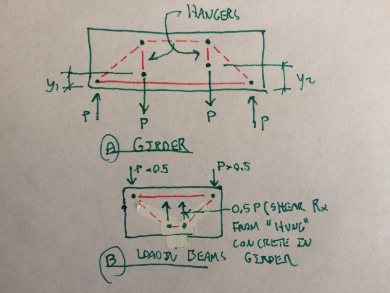
1. Thank you for pointing out. So, the revised truss idealization should be as either one of belows. Any additional comment would help.
STM_Idealization_B-1_gtxvyj.jpg

2. Can you add more what you see inducing torsion? As it's shown, BEAMS are symmetrical in terms both of geometry and loading about the center line drawn in the picture right above.
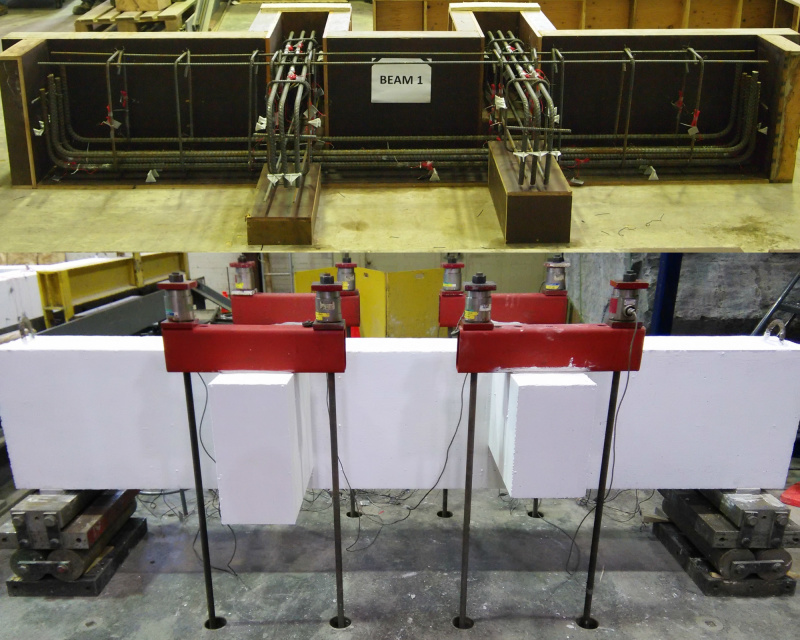
3. If you see any better idealization or simplification of this load transfer in this reinforced GIRDER-BEAM-joint, please give your opinion. I would be excited to hear you. For this, I add some more details of my specimens.
combine_images_a5b3tp.jpg

4. The purpose of this spring is to allow rotation/displacement of the part(sub-assembly) that I want to idealize. And the purpose of this rig (specimen or sub-assembly) is to resist vertical load with indirect support likewise girder does for spandrel beam.
5. I think you are on the same page with me as a matter of GIRDER's role. I see much less contribution of GIRDER in my idealization than it really does in real test. So, that's my problem and I'm looking for a better idealization other than FEM.
As I mentioned above, no torsion would occur by the way.

Thank you for all that you brought out, It would be pleased listening to you more.
 
Ratp,

I would like to clarify what I referred to by the term, "hanger reinforcement" that it is in accordance with 11.2.12 of CSA A23.3-04. You will easily find it is different from what you meant, stirrups across shear crack of ACI R11.1.3.1. Anyway, thank you for sharing your opinion and I would like listening to you more.
 
Your STM with a spring is ignoring the middle rotational restraint that the test rig will have from the girder's top and bottom chord strut and tie, respectively.

If you want simple, just use 2D for the STMs and hang your beams at the top of the girder where they intersect (the test rig has stirrups at/near the intersection - use them).

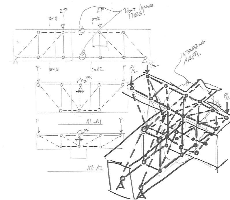
If you want complicated 3D, I'd say focus at the intersection area between beam and girder and add some elements to refine the model. You will have bending in 2 different directions here creating a saddle

stm_girder_bm_rr9p3c.jpg


The torsion I've noted will be a minor twisting due to vertical loads on a rotated beam (rotation due to deflection of the girder). I predict failure to occur on the top face of the shallower beam near the edge closer to the middle of the girder.
 
Which one fails first will depend on the M:V ratio of the loading beams. For low values, I'd expect the deeper beams to have more capacity. For higher values, I'd expect to get more from the shallower beams.

Like Teguci, I think that you're better off here in 2D.

image_vvkd8b.jpg


I like to debate structural engineering theory -- a lot. If I challenge you on something, know that I'm doing so because I respect your opinion enough to either change it or adopt it.
 
Baek,

I beg to disagree. It is exactly the same. Maybe the wording in ACI could be clearer, but that is the case in many areas. My interpretation of the ACI commentary is that hanging reinforcement is required, as is also required by Eurocode and As3600 as well as the Canadian code.

PS if this is research for a PhD or similar, I doubt that you should be asking us about it!
 
@rapt: your interpretation of the ACI provision is an interesting one. And I like it. However, in the decade that I spent as a structural engineer in the US, I only saw hanger-ish style reinforcing used a couple of times. Both were by very smart cookies and for the design of serious transfer beams. Unfortunately, the ACI commentary provision doesn't seem to make it sufficiently clear to designers that a beam to beam connection is an instance of a load applied to the bottom of a member.

I like to debate structural engineering theory -- a lot. If I challenge you on something, know that I'm doing so because I respect your opinion enough to either change it or adopt it.
 
@Teguci, @ KootK, @rapt
I really appreciate sharing your valued opinions and expertise. It was helpful indeed. I'm ashamed that I offended a posting rule which prevent students from writing about these. It's for my degree project. I would like you to kindly understand and suppress your enthusiasm on this technical issue at least to this thread.
 
Baek said:
I'm ashamed that I offended a posting rule which prevent students from writing about these.

Eh, I consider this a grey area really. Do we help with homework? No. Do we help with research? I don't see why not ethically. I consider research to essentially be "work" as anyone who's attempted it will surely agree.

I like to debate structural engineering theory -- a lot. If I challenge you on something, know that I'm doing so because I respect your opinion enough to either change it or adopt it.
 
Kootk,

Part of the problem is that people regard Design Codes as text books and design handbooks, and unfortunately they tend towards that over time as more and more "garbage" is added. A good concrete code should be about 10 pages long!

A design code does not detail how to design. It details limits and allowed short cuts to make design life easier.

Design theory is covered by textbooks and engineers are supposed to understand how to design based on those.

Too many are playing legal games these days saying that the code did not tell me I had to do it so I do not have to. Design Theory is what tells you how to design. If an engineer does not understand statics and design theory he should not be designing (and I hope he is not using RAPT because it assumes the user knows what he is doing).

I had this "hanging reinforcement" argument with a "superior" in the 1980's insisting that it was required in a design with primary and secondary beams. His argument was that the AS code at the time said nothing about it. My argument was that design theory required it. He was the boss! Eventually, the other partners in the business had a big meeting about it and a couple who could read text books agreed with me and I won in the end and company policy from then on was to provide hanger reinforcement! Fortunately it is now mentioned in AS3600. Interestingly, he was a steel designer and a steel designer always "lifts" loads applied at the bottom to the top of the member.

Looks like US engineers had better go back and learn their design theory rather than how to use computer software and get around code rules.

RE Students, this is an ongoing discussion. In my opinion
A students Thesis or PhD is supposed to be his own thinking, not ours! His research behind it should not be based on questions to engineers, it should be research! If he is going to go on and win a Nobel price and a couple of million, he needs to earn it. And if he is going to run around saying he has a PhD for his development of a theory it has to be his development of the theory, not ours (substitute gender neutral for his where appropriate).
 
rapt said:
Looks like US engineers had better go back and learn their design theory rather than how to use computer software and get around code rules.

In the interest of full disclosure, I designed a lot of concrete beams before I returned to Canada, flipped open CSA A23, and went "I gotta do what now?". Most of what most of us do is what our mentors and colleagues do. It's always been that way and I suspect that it always will be that way. There's just too much to know for folks to get 100% versed in the finer points of all things before they jump into production.

Based on my discussions here and in the real world, I'm convinced that eight of ten practicing engineers don't understand the difference between rebar development and rebar anchorage (my personal hot button issue). It's a rather fundamental thing yet everybody seems to get by just fine without understanding it in a fundamental way.

rapt said:
A students Thesis or PhD is supposed to be his own thinking, not ours!

I believe that a student's thesis is supposed to be a synthesis of whatever knowledge currently exists in the wild and that student's own, unique ideas and disoveries. I consider querying knowledgeable professionals like us to essentially be an extension of the lit review process which is integral to thesis development.

I like to debate structural engineering theory -- a lot. If I challenge you on something, know that I'm doing so because I respect your opinion enough to either change it or adopt it.
 
Kootk,

I was taught at university that loads applied at the bottom had to be lifted to the top first as all beam design theory is based on top loading.
I would have thought that anyone who has studied truss analogy or strut tie would pick that up immediately.

I suppose I decided for myself that side meant through the compression zone which is at the bottom so it was effectively bottom. Technically any load carried by shear reinforcement in the secondary beam is already lifted to the top, so it is only load carried by the concrete that must be lifted!

I think a lot of it has to do with the education systems. I think there is now too much emphasis on teaching how to produce design than there is on the fundamentals. Maybe these days a lot of the teachers in the universities have the same lack of understanding as the mentors you mention.

 
Status
Not open for further replies.

Part and Inventory Search

Sponsor