Eng-Tips is the largest engineering community on the Internet

Intelligent Work Forums for Engineering Professionals

Stuck on this Frame analysis. 3

Status
Not open for further replies.

Bogusbogedi

Structural
May 31, 2024
13
0
0
MU
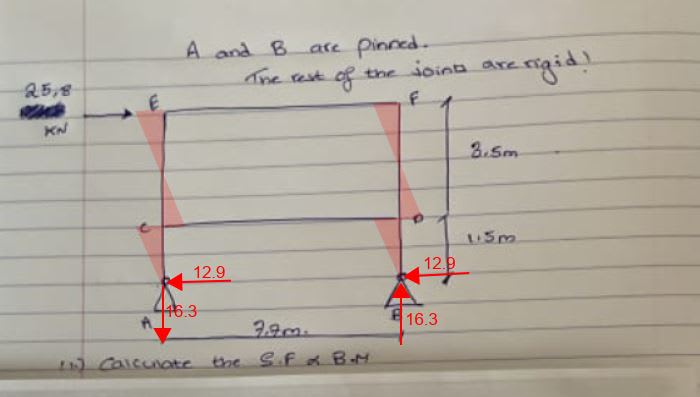
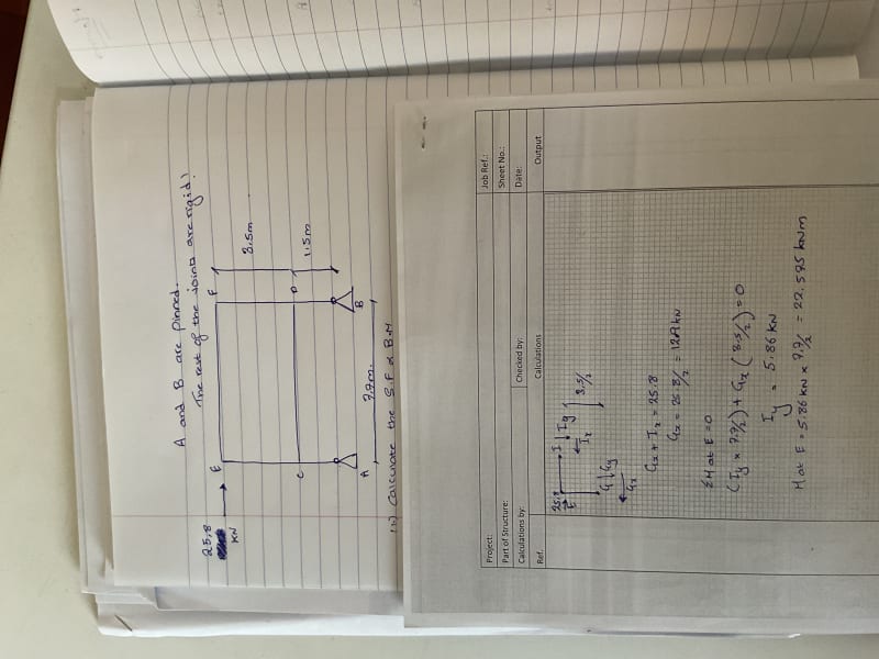
Stuck on a Frame analysis.
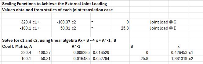
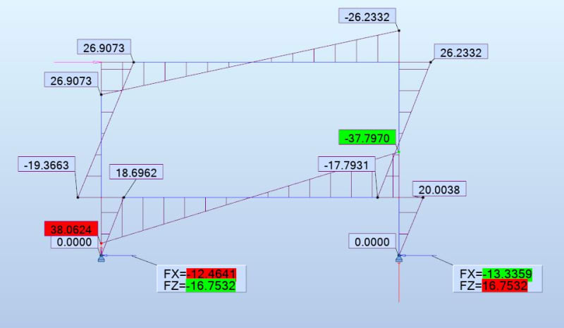
I keep getting a moment of 22.6 KNM whereas using the prokon frame analysis module I keep getting around 32.
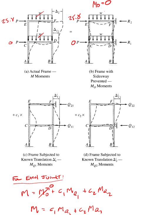
I analysed the frame without the sway correction as of yet, but I genuinely do not feel it would amount to such.
I have tried introducing points of contraflexire between the rigid joints but can’t seem to match the software analysis.
Kindly let me know what I am possibly doing wrong.

image_wjhlmv.jpg
 
Replies continue below

Recommended for you

joints E and F are fixed right ? ('cause A and B are pinned)

why isn't the moment 25.8/2*5 = 64.5 kNm ? (without the swaybrace)

"Wir hoffen, dass dieses Mal alles gut gehen wird!"
General Paulus, Nov 1942, outside Stalingrad after the launch of Operation Uranus.
 
Depending on the stiffness of the beams and columns, the column moment diagram is going to look something like the red shaded areas in the sketch below. It is clear that the maximum beam moment will be at points C and D and will be greater than 22.6 because of the contribution from the reactions at A and B.

Review your textbook to find out how to handle sidesway in frames.

Capture_g3lado.jpg
 
so the ground (vertical) reactions at A nd B are what they are ... 25.8*5/7.9, and this is the load in AC and BD.
But the load in CE and DF is much smaller because the moment is taken out by CD.
CD's loading is two moments (and the ends) with the same sign, reacted by a couple.

And the moment taken at C is dependent on the stiffness of CD ... the stiffness of CD is not only keeping the angle between CD and AE as 90 deg (though this is more a function of the joint design), but it is also stopping CD adopting an "S" shape.

"Wir hoffen, dass dieses Mal alles gut gehen wird!"
General Paulus, Nov 1942, outside Stalingrad after the launch of Operation Uranus.
 
@BAretired Thank you for your valuable reply.
I have been using Hibbeler for my analysis, it works be great if you could point me to a specific book to use.

I do understand the moments at Joints where the bracing after would be greater.
I’m unable to wrap my head around how to break this frame into Free body diagrams set points of Contraflexure to be analysed.
 
@rb1958
From my understanding the stiffness K = EI/ L
assuming E and E are constant won’t that mean that K = 1/ L, so if the beam shown is 7.7 m
won’t that make it less stiffer?
 
if the two vertical legs are the same section, if the joints are equally fixed .. then why not.
this being a problem, the assumptions should be stated.
In my "real world", we might often assume a 60/40 split, and conservatively either split (40/60 or 60/40)

I believe the analysis assumes that joints C and D are not rotating (more than assuming the CD is perpendicular to AE).

"Wir hoffen, dass dieses Mal alles gut gehen wird!"
General Paulus, Nov 1942, outside Stalingrad after the launch of Operation Uranus.
 
Bogusbogedi said:
I have been using Hibbeler for my analysis, it works be great if you could point me to a specific book to use.

I hesitate to recommend specific books, as I am not familiar with most of them. The Hibbeler text may be perfectly adequate for your purposes. The book I used prior to retirement is "Statically Indeterminate Structures" by Chua-Kia Wang, PhD, published by MGraw-Hill in 1953. If that is available, I recommend that.
 
GregLocock said:
BAretired although it seems reasonable as an assumption that the horizontal reaction at the pinned joints is split 50/50, I can't quite justify it.

You may be correct, but I would have to review Wang to see how it would be affected. If I remember correctly, in cases of sidesway, there are some corrections to be made to account for movement of joints. My guess is that the horizontal reactions would be pretty close to 50/50.
 
My general question remains as to how to proceed with the analysis, do i break the frame into smaller members by introducing points of contraflexure between the rigid joints.
The moments in member EF and EC are around 30 KNm and in the CD member slightly higher at 32 KNm(from software analysis)

Regarding the behaviour of the frame under the lateral load, I understnd that the joints at C tend to open more (as compared to E) due to the pin support at A.
Hence to resist the joints opening a larger moment would be required at that joint.

How would we proceed with analysing the frame by hand?
 
Review the moment distribution method for sway frames in the Hibbeler text, section 12.5 in the 8th edition. Slope-deflection method would be another hand method as well.

That will get you closer to the software answer, the additional difference will be due to the axial deformation effects of the members. Another possible source of difference might be shear deformation if the software considers it. For textbook problems like this where the member properties are not intended to influence the results use very stout sections and make sure the results you are looking at do not include member self weights.
 
Here it is using the MDM-Sway procedure:
Capture_tgf0au.jpg


MDM for Joint C displacement (Mq1 model)
Assumes a moment for the upper column of 6EI delta,E / (3.5)^2 = 100 kN*m, fixed end moment for the lower column is scaled accordingly:
Note I only did 5 cycles of MDM so that will impact the final answers a bit.
Capture_qvewuq.jpg


MDM for Joint E displacement (Mq2 model):
Capture_ehmb9l.jpg


Solve for the c1 and c2 constants in the joint load scaling functions:
Capture_y40lcv.jpg


Final Joint Moments:
Capture_junxb6.jpg

From here you can see the top column moments aren't symmetric so the mid-height inflection point assumption of the portal method is not accurate for this case.

Analysis Program with large members to limit secondary effects:
Capture_ddslen.jpg
 
hummm ... so shear reaction is not 50/50 ... hummm ... because the two verticals have the same stiffness, but the far one sees the axial stiffness on the frame member (EF) ... therefore is slightly more flexible than the direct loadpath ?

"Wir hoffen, dass dieses Mal alles gut gehen wird!"
General Paulus, Nov 1942, outside Stalingrad after the launch of Operation Uranus.
 
Good one, Celt83. I am surprised that the axial stiffness made even that much difference in FX.
If the height is 5m and the span is 7.9m, FZ should be 25.8*5/[highlight red]7.9[/highlight] = 16.3291; you found it to be 16.7532.
I don't know why there is a difference. (7.9 should be 7.7)

Using hand methods, the axial deformation was ignored in my day, but perhaps in some cases it should be considered.
 
"I am surprised that the axial stiffness made even that much difference in FX."

To clarify my hand calc. did not include axial stiffness and in the software I used large members to make the impact of the axial deformation negligible I also disabled shear deformations.
 
The span is 7.7 m I apologise for the poor handwriting and photo.

@Celt83
Is there a reference book I can use as a guide to understand the sway model and the moments at the joints as you have mentioned, I will use this as a guide to develop my own personal excel sheet.

I am slowly understanding the frame behaviour thanks to all of y’all.

 
Status
Not open for further replies.
Back
Top