Continue to Site

Eng-Tips is the largest engineering community on the Internet

Intelligent Work Forums for Engineering Professionals

  • Congratulations KootK on being selected by the Eng-Tips community for having the most helpful posts in the forums last week. Way to Go!

Stuck on this Frame analysis. 3

Status
Not open for further replies.

Bogusbogedi

Structural
May 31, 2024
13
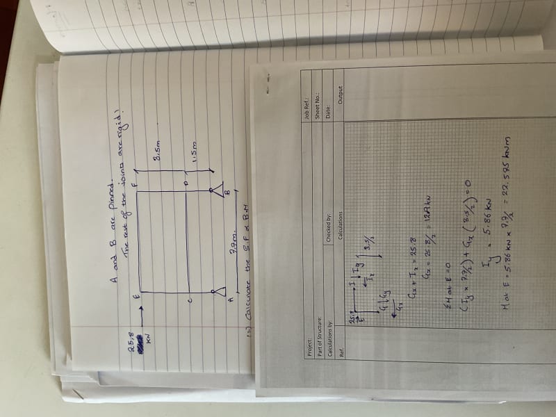
Stuck on a Frame analysis.
I keep getting a moment of 22.6 KNM whereas using the prokon frame analysis module I keep getting around 32.
I analysed the frame without the sway correction as of yet, but I genuinely do not feel it would amount to such.
I have tried introducing points of contraflexire between the rigid joints but can’t seem to match the software analysis.
Kindly let me know what I am possibly doing wrong.
image_wjhlmv.jpg
 
Replies continue below

Recommended for you

Celt83, I got a problem.

Consider the question as given, and its mirror image. Now add the two together.
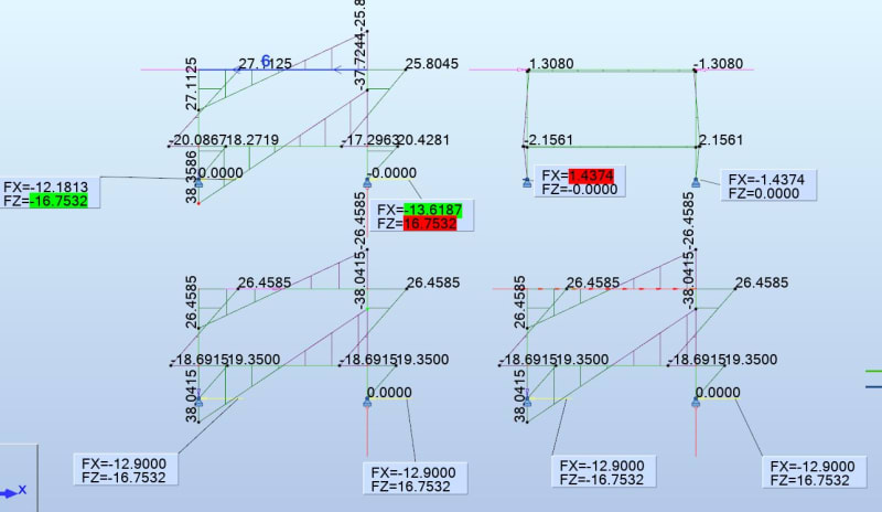
We hav e net compression of 25.8 in the top member, and no forces anywhere else.

yet if we add the reactions for each pinjoint, at the left we have -12.46--13.33=0.7 kN

same at the other side -0.7 kN

Is this due to axial compression of the top member springing the posts apart at the bottom?


Cheers

Greg Locock


New here? Try reading these, they might help FAQ731-376
 
Incidentally this answers my own previous question to BAretired, in the absence of compressive effects the reaction at each pin will be the same size.

The reason is that in the absence of compression, we are agnostic about where the force is applied to the top member, so split it into two and apply half at each end of the top member. Now cut the structure down the middle and we have two essentially identical structures taking into account various sign changes, hence the reaction force must be equal.

Cheers

Greg Locock


New here? Try reading these, they might help FAQ731-376
 
Greg:

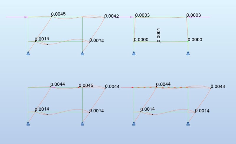
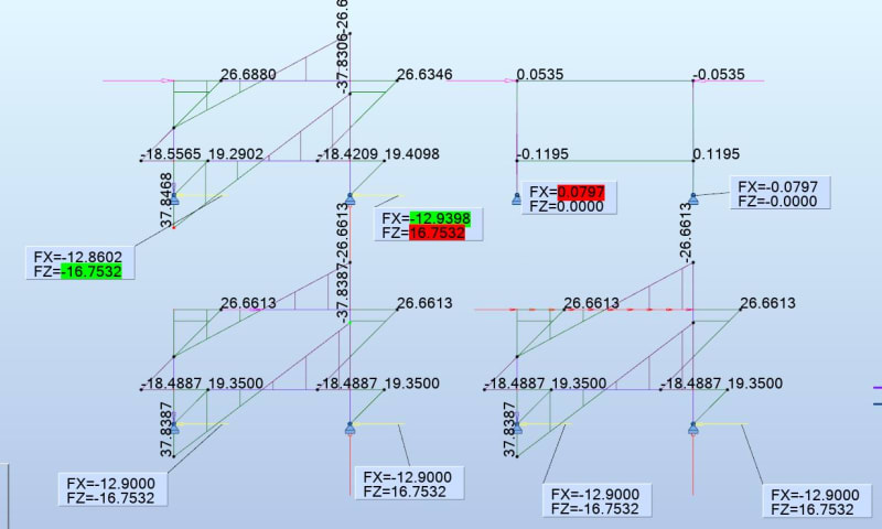
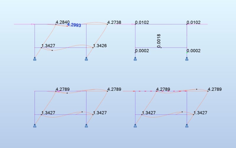
Interestingly enough it seems this structure is sensitive to the axial rigidity of the members when the load is applied to the corner nodes only.
Models:
[pre]25.8kN applied to upper left node 25.8kN applied as opposing forces to upper corner nodes
25.8kN applied to upper beam mid span 25.8kN/7.7m applied as a uniform axial load to the upper beam[/pre]

@infinite/nearly infinite axial rigidity (W44x335):
Capture_vh0n02.jpg

Capture_rqdnph.jpg


@Soft axial rigidity (W8x10):
Capture_uhtflp.jpg

Capture_uwubgc.jpg
 
hummm, maybe people who harp on about "validate your model" are onto something ?

"Wir hoffen, dass dieses Mal alles gut gehen wird!"
General Paulus, Nov 1942, outside Stalingrad after the launch of Operation Uranus.
 
So with the top left one, if we add that to its mirror image we should get the top right one.
So for the LH pin joint we'd get -12.2-(-13.6)=+1.4, and for the right -13.6-(-12.2)=-1.4

and top right agrees.


Cheers

Greg Locock


New here? Try reading these, they might help FAQ731-376
 
Thank you all that have helped me.
@celt83 I was able to understand most of it following the Hibbeler book and resource material found here :
Some final thoughts before I close the thread would be regarding the behaviour of elements under loadings and how these rotation or displacement formula were derived in the first place.

Thank you all.
 
Celt83 said:
Assumes a moment for the upper column of 6EI delta,E / (3.5)^2 = 100 kN*m
I can't catch this, can you elaborate more on this? Shouldn't it be read as 6EI big_delta/L^2
 
Status
Not open for further replies.

Part and Inventory Search

Sponsor