Eng-Tips is the largest engineering community on the Internet

Intelligent Work Forums for Engineering Professionals

  • Congratulations waross on being selected by the Tek-Tips community for having the most helpful posts in the forums last week. Way to Go!

Sub-grade preparation for Vibration Isolation

Status
Not open for further replies.

enriko12

Industrial
Sep 5, 2020
54
0
0
US
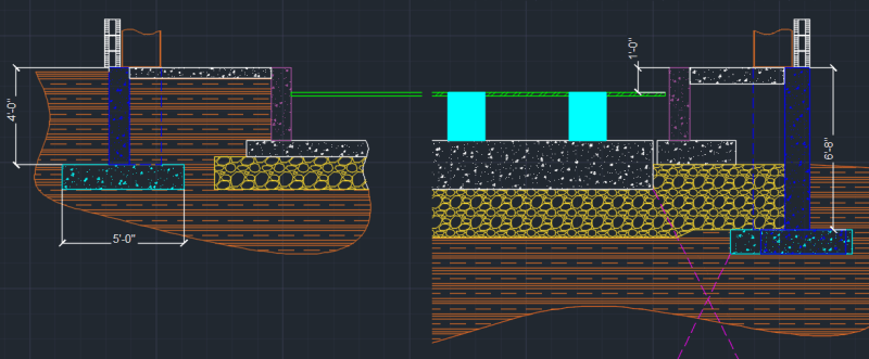
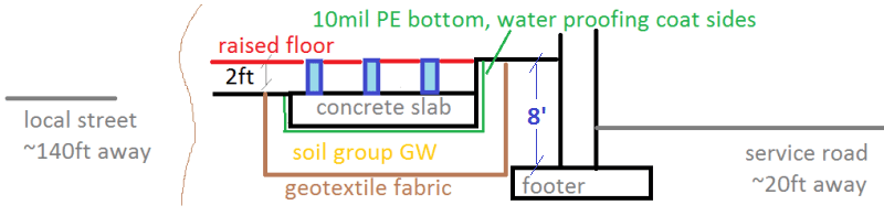
We are building a vibration isolated slab for sensitive scientific equipment. After reviewing a lot of literature, I see that anywhere between 1 ft to 8 ft of engineering fill were used, sometimes geo-textile fabric was also mentioned, but no details. I feel like its more of an art than a true science and would love to get some opinions on what would make sense and what would be a questionable investment.

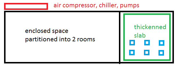
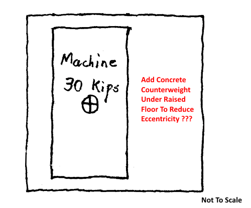
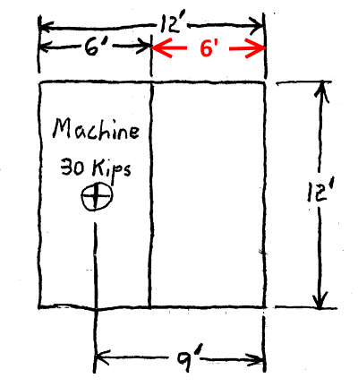
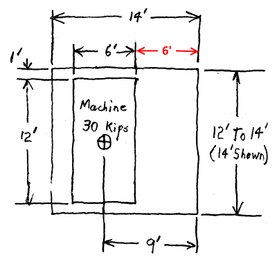
So basically we are pouring a 12x12 ft slab, 4ft thick. Idea is to keep low frequency vibrations to the minimum. Equipment will be further installed on pneumatic vibration isolators, so that will take care of higher frequencies fairly well. Soil on site is some sort of clay with traces of organics. Main source of random vibrations is local road with occasional truck traffic, approximately 140 ft away. Also some mechanical equipment (e.g. chiller, rotary air compressor) is supposed to be installed as close as 20ft away. I planned on putting those on springs insulators and on a dedicated 12" thick slab

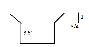
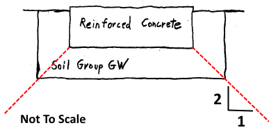
Would it make sense to excavate an additional 4 to 6 ft and fill with compacted gravel, geo-fabric, etc, or 1 ft of gravel would be just as good enough? Would gravel be the best material to use for the fill?
 
Replies continue below

Recommended for you

seriko12 - Here is my sketch of the 12' x 12' slab. Note the 6' (shown in red) allowance for "control cabinets and operator space", per your description. The 30 kip machine load has 3' 0" eccentricity and the center kern is 4' 0". For now, ignore any live load, weight of control cabinets, concrete pedestals, etc.

12x12_Slab-400_u6vikc.png


Here is an example of what I mean by "adjusting the geometry" and "designing backwards":

Try 14' x 14' slab dimensions (since that is maximum size that may fit inside the existing building).
What is important is the 6' space for system operation - all other dimensions are derived from that. Note that 30 kip machine load eccentricity has been reduced from 3' 0" to 2' 0" and the center kern has been increased from 4' 0" to 4' 8"... both desirable characteristics.

14x14_Slab-400_q87vok.png


I have a hunch that optimum slab size will be 13' x 13'. For those dimensions you calculate three things:

1) Eccentricity of the 30 kip load.

2) Eccentricity of the 30 kip load combined with the dead load from each of two assumed slab thicknesses (24" and 16"). We'll discuss these two thicknesses later.

3) Using this combined eccentricity, calculate the soil bearing pressure profile for the slab.

Note: This is not a "make work" exercise, you need to have an idea of how slab is loading the soil. Also, I mentored six engineers, one at a time, to handle this type project. If you don't get involved yourself, you won't learn a thing.
There are plenty of other criteria to consider, but I don't want to "dump" it all on you right now.

[idea]
 
Here is what 13x13 slab looks like:
loads_aaspf7.png

I assumed that the ratio of soil bearing pressures on both sides should be minimized, hence the heavier the better (as long as soil bearing capacity allows). That's how I came up with 48" thick slab to begin with. Am I missing something?
 
seriko12 - No, you aren't missing anything; just more competing constraints from squeezing a large slab in a small building:

1) The slab needs "thick" subgrade, but the depth of excavation inside the building should not go below the elevation of the bottom of the footings. You don't know that depth yet, but the more concrete the less subgrade.

2) The slab needs to be rigid. While increasing slab thickness will make it more rigid, the law of diminishing returns kicks in.
The 16" thickness is my estimate of the minimum thickness that will be suitable for both a 30 kip load and rigid enough for successful vibration isolation.

3) If the slab is "thin" and sufficient subgrade thickness can be installed the depth of excavation can be reduced. Excess excavation inside the building is going to be expensive... blowing the budget.

4) Excavation is going to be very close to the building foundation. The deeper the excavation, the more risk... which the Contractor will have to take steps to mitigate... driving up cost. If excavation is too deep (usually 4') OSHA regulations kick in that will really blow the budget. Note that when I first posted, suggested looking at 2' of concrete plus 2' of subgrade... that was intentional.

What is really needed right now are the interior dimensions of the building (preferably the clear span between foundation walls), as-built or estimated projection of building footings into the interior, and as-built or estimated elevation to both top and bottom of the footings. I know that's a tall order, but without some info to go on everything from here on is a pure guess... which, if wrong, will blow the budget or result in an unsuccessful project. Perhaps investigate what is typical for similar buildings in your area.


[idea]
 
Eight feet, good. Now I see why 2' of concrete is not a concern (that distance would be about 2' here.) You are ready to pick a slab size and proceed; a few more suggestions:

1) With much of the floor removed and excavation underway, the foundation will tend to become a cantilever retaining wall. Monitor the foundation for movement and don't put heavy items or equipment adjacent to the building exterior. Avoids a surcharge load on the "retaining wall" (foundation).

2) Compromise on width of gravel at the slab perimeter, if needed. Try have enough for the gravel subgrade to fully distribute load to underlying soil:

Subgrade_Width-400_wygepc.png


3) Pedestals should be fine, keep the height/width ratio at a low value.

4) Keep an open gap between slab perimeter and adjacent building floor. Turbine-generators do this for vibration reduction. In this photo, turbine-generator pedestal is painted blue, about an 1.5" air gap between pedestal and surrounding floor:

Steam-Turbine-400_roc78g.jpg


5) Keep a similar gap between raised floor on the slab and surrounding raised floor.

6) Equipment pedestals are typically a little wider than the footprint of the equipment (we use 3" all around). This allows tolerance for pedestal construction and equipment placement. Also, keeps the equipment footprint inside the pedestal rebar cage. Do this for the floor supporting the 30 kip machine and any pedestal mounted equipment.

7) I assume provisions for transporting and installing the 6' x 12', 30 kip machine don't require special features to be included in this project.

Believe you will get good results.


[idea]
 
1). This is a huge concern. Grade beam is acting as a retaining wall as built, and while removing some soil on the left side will reduce lateral pressure, it will also reduce the weight of the soil on top of the footing. This soil is what helps with overturning and reducing eccentric loading due to moment frame kick out. It does not help that concrete contractor went ahead with taking the old slab out, and now hairpins are exposed and nothing ties 2 ends of the moment frame together, so foundation alone is handling the kick out, which it was not designed to do.

4). I was going to specify 2" closed cell foam in the gap, to make it fool proof against dropped tools etc. Air gap makes me very nervous, very likely contractor will accidentally drop at least some gravel in before backing rod and sealant is applied.

3). Pedestals do limit the flexibility of moving equipment at a later date. One advantage is that whole slab can be level with the bottom of the subfloor tub. If we raise the slab up, there are 2 additional issues - entire left side is facing open space, unless we make it thicker than 24". For some reason I prefer it to be embedded a little. 2nd issue is that pressure cone at the footing plane is increasing as the slab height increases, and will likely overlap the footing.

6). In addition, I would probably like to add some sort of cross bracing to interconnect all 6 pedestals in both directions.

7). There is no overhead crane, so rigging 30 kips on top of pedestals will probably cost a fortune, but it is outside of the scope.

I will sketch a floor plan once exact size of the footings is known, but I am cautious of any kind of exploratory digging due to #1 above.
 
3) With the footing at a depth of 8', will be hard to avoid superimposing slab load on the footings. The slab is so close to the building.
I don't see it as a major problem at that depth, slab loading is low, << 1 kip / ft[sup]2[/sup], and that will have been somewhat distributed at that depth.

4) For your application, closed cell foam seems a good compromise. I would form the gap, then insert the foam later instead of using foam to create the gap. A turbine floor is elevated with gap going completely through it - anything getting in the gap either falls through or can be forced out the bottom.

6) Doubt that is needed. With a thick slab, should be no problem to anchor robust pedestals securely. All of ours are "stand-alone" pedestals and many have pretty large / powerful rotating equipment on them. Cross bracing "could" be subject to resonant vibration.

Edit: 1) Since this is a temporary condition, reduced loads in ASCE 37, "Design Loads on Structures during Construction" may apply.

[idea]
 
I am banging my head against the brick wall regarding #1 for a week already. The new slab goes right in between the columns, so there is no way to tie the opposite ends of the moment frame directly, and by nature of the isolated slab, nothing should be tied into it either. And with no room left between the slab and the wall, options are extremely limited.
Design around existing structures is always fun
 
SlideRuleEra, I got a feeling that you really prefer a pedestal solution instead of top of the slab being flush with the floor. Any pros or cons I have not thought about?
 
seriko12 - I guess I'm biased. Pedestals make a lot of sense in a generating station, but there is no way I can have enough info to recommend them, or not, for this project. In general terms, there are two features of this proposal that bother me:

1) Eccentric loading of the soil seems excessive...700 PSF on one side, 300 PSF on the other. I can't demonstrate that this is "bad", but it sure does not seem "good".

2) System operators and support equipment are on the isolation slab with the machine. Walking and operating equipment are two of the worst culprits when minimizing vibration.

A potential solution to both of these issues could be to use the isolation slab for only the 6' x 12' machine:

IsolationSlab-400_jagtjv.png


1) Slab may be designed so that centroid of the machine aligns with centroid of the slab... virtually eliminating eccentricity. Important to make the alignment to the machine's centroid, which is not necessarily the the center of the machine's footprint. Doing this could require either an elongated or trapezoid shaped isolation slab.

Trapezoid-200_ystad8.jpg


2) Operations & support equipment would no longer be on the isolation slab.

Also, I suppose this proposal could result in some cost savings compared to a larger, more complex slab.

[idea]
 
I am trying really hard here to give enough details without violating NDA with a client and giving out any clearly identifiable information. The operator wont be present on the slab during operation, only to load and unload samples which requires 6' clearance. There is a new partition wall enclosing the thickened slab, plus an additional adjacent room. Because of 2ft drop, I will need a perimeter wall on 3 sides of the slab. Here is what I have so far, pending details on hairpins/foundation reinforcement
plan1_uzcdyt.png

plan_fssdej.png
 
seriko12 - Hmmm, always more complicated than expected. No operator present takes away my second concern.

Since soil bearing pressure for the slab is low, additional weight is not a big problem. Would it be practical to add concrete counterweight to reduce eccentricity?

Counterweights-500-1_ajmsrv.png


[idea]
 
I see, you mean a removable counterweight on top of the slab. that should be doable. Any vibration related issues with the gravel fill extending all the way from the wall and under the entire thinner slab on the left?

My other concern is waterproofing, underlying soil is very wet, you can see water at around 4ft below grade and only 1 ft outside of the building in the rear. So the new gravel fill will probably get soaked. And since it all gets painted with epoxy, cant tolerate much moisture coming through the concrete.
 
seriko12 - I was thinking of a permanent counterweight (to reduce chance of vibration), but trying a removable counterweight is probable a better idea. I did some rough calcs, concrete counterweight will have to be pretty large but should be able to remove all eccentricity.

Don't see any concerns with gravel fill everywhere. I would use the same thickness of gravel plus geotextile fabric everywhere.

If it's surface water, maybe a drainage system will help. If it's ground water, (considering the budget) install the vapor barrier and live with the results. For several good reasons, some of our generating stations are build on the edge of swamps. For design, we assume the water table is at ground level... it is after heavy rains. You can't pump or drain a semi-infinite amount of water and "dry" things out.

[idea]
 
So lets say we have a 2ft or so of well compacted GW gravel covering entire area and then 1 common slab taking most of the area (partition walls, personnel, non-sensitive equipment), 1 isolated thickened slab (sensitive equipment), and 1 smaller thickened isolated slab (noisy equipment such as air compressor and water chiller). The biggest concern is low frequency vibrations - 10 Hz and under, and especially < 5 Hz. Would not those propagate through the gravel?

Regarding waterproofing, I am afraid that vapor barrier might not be enough. It works well with damp soil, but in this case, entire slab will be below water table. Any recommendation on the next most cost effective solution? Some sort of a continuously sealed membrane which could be put directly on gravel without adding a mud slab first would be ideal.
 
Step back and take a look at the existing conditions and requirements that have unfolded:

1) Concern is about nearby traffic and operating equipment.

2) Existing slab vibrates noticeably when people walk on it.

3) Existing building footings are 8' deep.

4) Proposed slab is below the water table.

From this information alone, I assume "good" soil is where the existing footings are located... 8 feet, or so, underground. For a "best efforts" project, I would say the gravel backfill should be that deep, otherwise, chance of a successful vibration isolation slab are "low". Of course, excavating to a depth of 8' will bust the budget and collapse the existing building.

Also, the project needs input from a geotechnical engineer and a vibration isolation consultant, but the budget does not allow for that expense either.

What are the consequences of staying within budget and having a project that is a failure? Seems it is time to discuss the situation with the client.

Concerning vibration < 10 Hz, the question is not will vibration at those frequencies propagate through gravel... I'm sure they will, but well graded gravel is as good as it gets for a high subgrade modulus. The real question is how much vibration transmission is acceptable?

Waterproofing is a relative term. We used bentonite based liners and sheets to "waterproof" ponds and below water table structures. Permeability for those product is really low, but not zero. Moisture removal, or accepting that there will be some moisture accumulation are reality.

[idea]
 
Things are getting more and more interesting. Now they want to lower the entire thing 1ft deeper to gain extra height on top and to bring the sewer and water pipes above the tub floor, otherwise they end up right in a middle of the slab. Also turns out footing depth and size were not probed correctly. The depth is 6' 8", not 8' in the rear and footings are 5' x 5'. If we assume water table at ground level in the back, it will be around the bottom of the main area slab. Here are updated details, do you see any issues with excavating to the top of the footing in the rear?
both_c7gqpb.png

slope_rtz5k2.png

P.S.: We don't know the history of this site, but the footings might have been placed on top of a fill. Few years ago we did an excavation about 4ft below ground 20ft away from the building, and ran into large chunks of broken up concrete slab buried at 3 ft
 
By the way, here is the mentality I am dealing with:
Suggestion 1: Lets double the concrete thickness and add 1 more layer of rebar - Awesome idea, go ahead!
Suggestion 2: Lets hire a specialized consultant and order soil borings - Are you out of your mind? I don't have a budget for that!
 
seriko12 said:
...do you see any issues with excavating to the top of the footing in the rear?

Depth of the footing was uncertain... 8', now 6'8".
Elevation of the water table is uncertain.
Soil properties are unknown, and may differ at various depths.
Existing floor has been compromised by a Contractor.
There is doubt if the foundations walls are adequate to act as a "retaining wall".

Never a good idea to perform excavation where the consequence of making an incorrect assumption is building collapse.
Add to this that there are precious few Contractors who are qualified to excavate safely under difficult conditions... although many will say they are.

What is the answer to the other question I asked: "What are the consequences of staying within budget and having a project that is a failure?"

Note: I'm not trying to "give you a hard time", but pointing out some of the potential pitfalls of proceeding based solely on assumptions.
You have a little more info now: the footings are 5' square, why not back-figure an estimate of the soil bearing pressure? If it is "high", maybe things aren't too bad. If it is "low", more caution likely needed.

[idea]
 
Status
Not open for further replies.
Back
Top