Continue to Site

Eng-Tips is the largest engineering community on the Internet

Intelligent Work Forums for Engineering Professionals

  • Congratulations KootK on being selected by the Eng-Tips community for having the most helpful posts in the forums last week. Way to Go!

Sub structuring in abaqus cae

Status
Not open for further replies.

Anvesh Kumar

Automotive
May 26, 2023
17
Hi all,

I am doing a contact, geometric non linear analysis of transmission parts (case , housing, cover etc...). Here i want to check the contact opening between case and housing parts.

Housing and CASE are connected through bolts and COUPKIN...

I want to use substructuring technique for this analsysis in abaqus cae.

Can anyone tell me the exact procedure to do the sub structuring?
 
Replies continue below

Recommended for you

You have to generate the substructure first: use the Substructure generation step, specify the identifier and prescribe the Retained nodal dofs boundary condition to nodes that will connect the substructure to other parts in the model. Then, after running this analysis, you can add the substructure to your model using File --> Import --> Part, position it in an assembly and attach it to other parts using constraints.

Substructures can be used in nonlinear analyses and undergo large motions when geometric nonlinearity is enabled but keep in mind that they can deform only in a linear elastic way.
 
thanks for your answer!
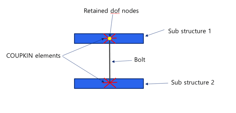
i have seleted the nodes of bolt ends as retained d.o.f nodes which are connected to COUPKIN elements between the CASE and Housing parts..

But after generating the substructure i imported the part in the new model but the sub structures are not connected at the specified bolt connection nodes.
if i try to submit the data check it is showing the unconnected regions are present in the model..
Is there any way to connect the two substructures at the Bolt and COUPKIN connections
 
substructure_gdoc48.png


Pleas refer the schematic of the assembly.. i have multiple bolts hence multiple retained nodes
 
If the blue parts are substructures then you have to retain their nodes to which the COUPKIN elements are attached.
 
okay what about the bolts.. will it be part of substructure 1 or sub structure 2
and once i run the generate substructure step and import the Sub_Z1.sim part file the COUP KIN elemensts assosiated to retained nodes are not present in the model
 
It depends on which parts of the model you want to treat as substructures. If only the blue ones then the rest should be treated as standard parts and added in the second analysis (substructure usage). If the bolt is also to be treated as substructure then you should perform a separate substructure generation f or it, retain its end nodes and then connect them with blue parts via COUPKIN elements added in the substructure usage analysis.
 
okay i have generated substructures for both the blue parts and bolts are considered as standard parts... but once i import the .sim files the substructures are not connected to each other and the COUP KIN elemenst are missing in the model why is it happening
 
You have to connect them manually (via COUPKIN elements in this case) in the second analysis using the retained nodes (defined in the first analysis).
 
after importing how do i connect the COUPKIN elements of Sub strutures 1 & 2 to the bolt end points
 
which means i have create manually the COUP Kin elements in abaqus CAE to connect the bolts ?
 
Actually, we are talking about COUPKIN elements but there are only distributing coupling (DCOUP) elements in Abaqus. You can define them in the second analysis but it's advised to use distributing coupling constraint instead. You could also use kinematic coupling or even rigid body constraint depending on your needs.
 
okay thanks for your support..
i would also like to know when do i need to create the actual loadcases like prtension and concentrated forces in the model..

Can i create the actual loads and boundary conditions after assembling all the sub structures
 
Substructure load cases can be defined at the substructure generation level, then these loads can be scaled at the usage level. Boundary conditions can't be included in the load cases, you have to retain proper DOFs and apply BCs at the usage level.
 
if there are any contacts present in substruture, do i need to create the contacts again in the usage level
i my case i have contact surfaces between sub structure 1 and sub structure 2
 
Substructure nodes that are supposed to be involved in contact have to be retained at the substructure generation level. Then you have to define contact at the usage level.
 
ok thanks for you help i will try it out with all your inputs..
 
Hi
My run is successful with substructure modeling.
But I have some doubts.
1) There are warning messages in the .msg file showing Zero pivot and numerical singularities
2) With the warning messages, sill my job completed and i got the results. Why is it so
 
Warnings are not errors, they indicate issues that may not have any impact on the results but a user should know about them. The messages that you got may indiciate underconstraint (unconstrained rigid body motions) so you should just make sure that boundary conditions and constraints are correctly defined and that the results appear to be correct.
 
actually i am comparing 2 model one is by using sub structures and other is without substructuring
The use of sub structuring is to reduce the solving time.. but in my case the model with sub structures is take more time to solve than the model with out sub structures
i guess because of this warning messages the solving time is increasing.. am i coorrect?
i have applied the same constrains and boundary conditions in both the models, still there are warning messages.. i dont understand why is it so?
 
Status
Not open for further replies.

Part and Inventory Search

Sponsor