Continue to Site

Eng-Tips is the largest engineering community on the Internet

Intelligent Work Forums for Engineering Professionals

  • Congratulations waross on being selected by the Eng-Tips community for having the most helpful posts in the forums last week. Way to Go!

Subducing Head:-pneumatic motor idea 6

Status
Not open for further replies.

Uncanny3

Mechanical
Feb 13, 2024
24
Hi,
I want to share my thought on what I have called a 'subducing head',
it's a pneumatic engine.
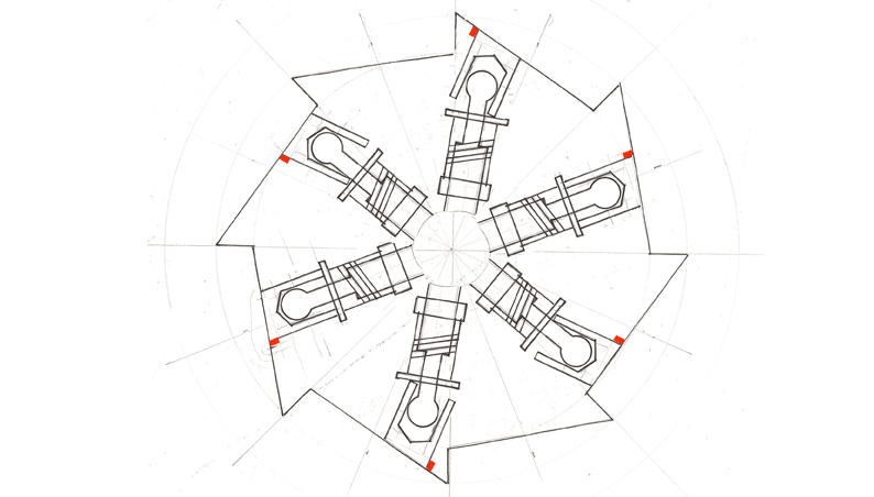
Here's the first drawing==>
gofund_me_power_areas_hand_drawing_u9msme.png

The concept is to apply more pressure on one side of a shape within an air compression chamber.
So the red squares are areas of pressure, which don't occur on the other side of the shape,
as the steps mating(wrung) allow the backward pressure face to be culled. Their area in practice ceases to exist.
However this does mean that the feet have to move uphill, and the air pressure will jam them outward,
meaning that inclination has to be overcome.
Would this provide circular movement?
-The thing about this motor, is that requires no more force than compression, it doesn't need relief.
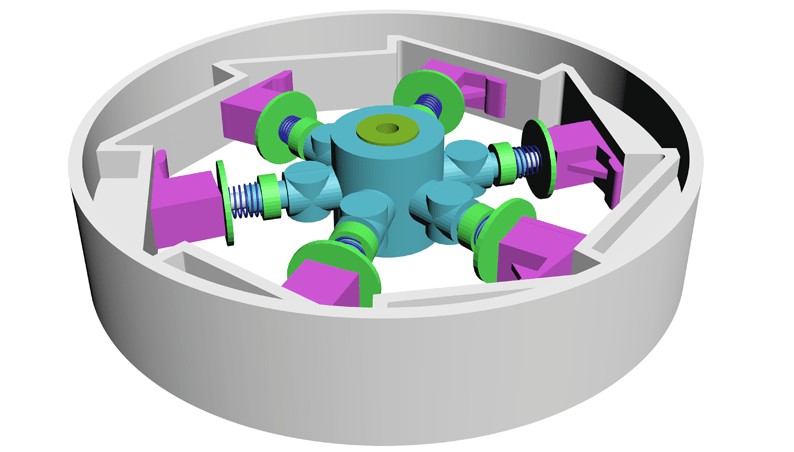
Here's a 3d model:-
gofund_me_perspective_v47foq.png

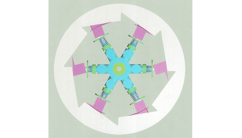
...and the forward pressure areas of such:-
gofund_me_power_areas_z8w6zf.png

I would like to share, and get this built. Do you think it would work?
...I'd love anyone to get involved
If you'd like to help, please reply with your thoughts
-I hope this is interesting,
if you would just like to comment on why or why this doesn't work,
I'd be curious to hear
Cheers
 
Replies continue below

Recommended for you

Eh?

Maybe someone better than me can actually understand where the air pressure is and how this thing actually creates force and movement.

To do work something needs to move and then pressure back up again. Needs a step by step drawing or animation.

Remember - More details = better answers
Also: If you get a response it's polite to respond to it.
 
What on earth is the objective of this complicated mechanism?

There's a pneumatic air motor in my shop, in the form of a CampbellHausfield pneumatic impact tool. It works, and I'm pretty sure its motor doesn't have anywhere near as many fiddly bits and pieces inside it! So, what's this supposed to do that existing technology doesn't?
 
Motors expand compressed air to extract power. Your diagram shows the red line getting smaller which is a compression. This is not going to work.
 
The pressure is inside the pipe-like mechanism.
The entirety of it is sealed flat between enclosing plates,
which would have a push fitting tapped into one.
There is no exhaust, this kind of motor theoretically works
without relief.
The compression is constant, the model is meant to cop 80-100psi,
of which even one square inch of forward area is a substantial torque.
So- with the plot, you can see that as the circumference becomes parallel to the round,
yes, the force stops, but there is more than 1/3 of surface area still pushing as there
are 6 spokes and 8 planes, providing a degree of offset and overlap, that moves forward,
theoretically at this stage.
The idea is that one side of these foot-like things captures more surface area than the other,
thus having momentum

There are all kinds of air motors, from turbos, vanes, volutes,
some have many parts, some don't

The advantage of this idea is that it's meant to work without relief,
just as long as there is no bleed through seals,
it can just keep going

thanks for your assaying and comment,
I look forward to any more
 
Errr pressure alone is not energy. You need flow and differential pressure to get energy.

You're making this sound like perpetual motion?

Remember - More details = better answers
Also: If you get a response it's polite to respond to it.
 
it's a motor of small principle,
that of subducing or redacting the normal and inherent
geometrical balance of shapes under air pressure
The plane allows the foot to catch a differential bias theoretically.
I can't call it perpetual motion here, but I'm happy that you have let me speak this far.
It will require maintenance of the teflon race, nylon feet.
The pressure will bleed some

I hope it's interesting

hmm, pressure may be an energy(not sure?), but yes, conventionally speaking without relief,
you cannot have movement.

This is something I have thought of, and it seems this site is a good sounding board
To practically assemble to see, I will fabricate and 3d print
 
I think Littleinch has condensed what is questionable about your motor. It appears your design has multiple points of sliding friction at the 'feet' (critically at the 'toe') and in the articulated joints' and presumably they must seal angainst the side closure plates. You may be fighting among many other issues huge frictional losses. 3D printing may not provide the proper surfaces. But if you have the printer and time . . .

Interesting design - good luck! Nice 3D model.
 
gibberish
/ˈdʒɪb(ə)rɪʃ/
noun
unintelligible or meaningless speech or writing; nonsense.
"he talks gibberish"
 
my gibberish on this one is just explaining a simple idea,
that probably doesn't work.
If a surface area is in a pressure chamber,
it uncontestably is pushed,
can one direction of surface fight another successfully if one has more area, further?

There is no seal at the side plates other than the rim, it's not needed in theory
-the spokes and feet need no seal to the enclosing plates

thanks for the compliment on the drawing,
there is some little friction, but I think quite little,
it will spin permissibly free under a hand push
-where a surface area will quickly gain 10's of kg

if you put pressure to a pneumatic ram,
equally to head and to rod, the head will push the rod out.
This non-sense is supposed to use the same principal,
of more Area having moving advantage
 
A surface in a pressure chamber is not pushed. Pressure acts on all sides of the surface and cancels the forces out. See divers in a hyperbaric chamber. They are not being pushed around any more than the rest of us.

A piston in a conventional engine is pushed because the pressure in the cylinder is higher than the pressure on the crankcase. The same pressure pushes in the head and cylinder walls but they are constrained and don't move so no work is done on them.
 
the sides of a pressure chamber are pushed imo,
a pressure chamber is required to be very strong because of this
compressed air wants to escape, it pushes at whatever wants to contain it
every vessel will blow out at some point, releasing the 'press'ure

every area in a pressure chamber is pushed the same though,
this is nearly the only way I have thought of to put different
pressures in square inches on the sides of a solid

usually the pressure is equal everywhere in a chamber,
but because the area under the foot doesn't exist somewhat(due to the flat mating),
a different pressure can be created, then therefore theoretically bias
can happen

yes a diver under manufactured pressure is of course not pushed around,
the pressure acts on them everywhere.

In this concept, pressure is not enacted everywhere, the outer of the foot is
redacted or subduced by mating it to the ratchet-like plane. It receives no pressure,
on the outer, the bottom of the foot
This lack of area theoretically creates bias,
because one side of the shape is larger in square inches
-it's pushed harder
 
No, that's not how this works.

I'd still like to know the purpose of this mechanism. One sentence, please. No word salad.
 
Uncanny3 said:
There is no seal at the side plates other than the rim, it's not needed in theory
-the spokes and feet need no seal to the enclosing plates
Yes, I have glanced back at your model and see your feet spring washers are larger diameter than the width of your pusher feet so obviously the sides of the feet do not seal against your side closure plates (not shown). What is not obvious is: is mechanism working as a fan - with each spring-loaded foot acting as a blade with a tip seal at each peripheral edge? If so, what are you trying to do better than an impeller or turbine can achieve?
 
BrianPetersen:
The intention of the mechanism is to be a very efficient motor,
if it worked it would generate electricity when coupled to a generator winding/dyno.

Brian Malone:
The mechanism is spinning hub, spokes and foot/scuffing blocks,
within the exterior housing. The feet will not have a gummy seal,
my intent is they will slide over the race, in a flat to flat mating.
The advantage is that it requires no more than
an initial pressure head, therefore requiring little to no fuel somewhat,
beyond compression needed to start it.
Whether a motor has advantage is a practical thing,
every type of motor should at least be designed perhaps

 
Your basic presumption (So the red squares are areas of pressure, which don't occur on the other side of the shape,) is simply not true.

You could feed this thing with 500bar of air and it won't move a single mm because there is no differential pressure.

Just because you can draw a red box and write that something exists doesn't make it so.

"The advantage is that it requires no more than
an initial pressure head, therefore requiring little to no fuel somewhat," This is definition of perpetual motion....

Remember - More details = better answers
Also: If you get a response it's polite to respond to it.
 
the idea is that redacted/removed outer face,
doesn't actually cause the pressure inside the vessel to change
-however the theory is that one side of the foot shape has more area
exposed to pressure,
meaning it must be pushed forward circumferentially

I have plotted the area demonstrably with more relevance to the actual
dimension in the coloured top view drawing.
The hand drawing is a concept communicator,
not the real areas, just the idea.
The coloured top view may be the actual area difference moreso

thank you all for your continued engagement
 
Maybe a slightly childish question here...

Take the mechanism just as drawn in your second and third diagrams - so no seals, and without having introduced any further pressure. Would you expect that to spin by itself? If not, why not, since it's already immersed in 15ish psi of compressed air?

A.
 
heya,
you're quite right, in one atmosphere it's copping pressure
-which is supposed to cause movement.
I hope it's device is amplified by a compression chamber state

I think I know what you mean
-like it's hard to conceive of this moving,
because whatever shape doesn't move in 1 atmosphere,
no matter how I could try to imbalance it

if a wedge moved, we would have used that a very long time ago

If this could absurdly work somehow,
I think that one atmosphere is not enough to break free of all of the frictive surfaces
braking. If we are under 15 psi all the time,
that is not showing on my dial indicators though

...and yes, what about under the ocean, 2 wedges are meant to slide off each other
under water pressure
 
Motors turn fluid pressure into mechanical power because fluid under pressure comes in from a high pressure source, expands and transfers energy into a mechanical device in the process of doing so, then leaves the device into a low pressure sink.

I'm not seeing that here. If placed under pressure with nowhere for it to go, it will sit there doing nothing, and no amount of hand-waving explanation will change that. Perpetual motion machines are not allowed, and unlike an arbitrary law of mankind that can be broken, the laws of physics cannot.
 
Status
Not open for further replies.

Part and Inventory Search

Sponsor