Eng-Tips is the largest engineering community on the Internet

Intelligent Work Forums for Engineering Professionals

Subducing Head:-pneumatic motor idea 6

Status
Not open for further replies.

Uncanny3

Mechanical
Feb 13, 2024
24
0
0
AU
Hi,
I want to share my thought on what I have called a 'subducing head',
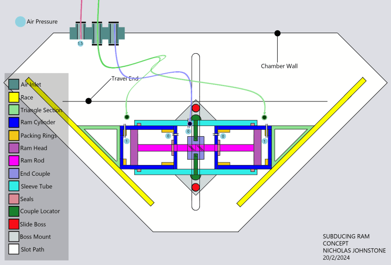
it's a pneumatic engine.
Here's the first drawing==>
gofund_me_power_areas_hand_drawing_u9msme.png

The concept is to apply more pressure on one side of a shape within an air compression chamber.
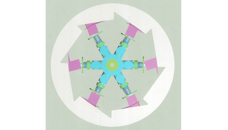
So the red squares are areas of pressure, which don't occur on the other side of the shape,
as the steps mating(wrung) allow the backward pressure face to be culled. Their area in practice ceases to exist.
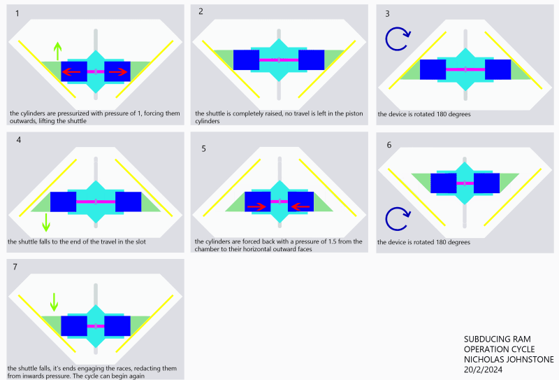
However this does mean that the feet have to move uphill, and the air pressure will jam them outward,
meaning that inclination has to be overcome.
Would this provide circular movement?
-The thing about this motor, is that requires no more force than compression, it doesn't need relief.
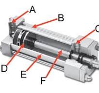
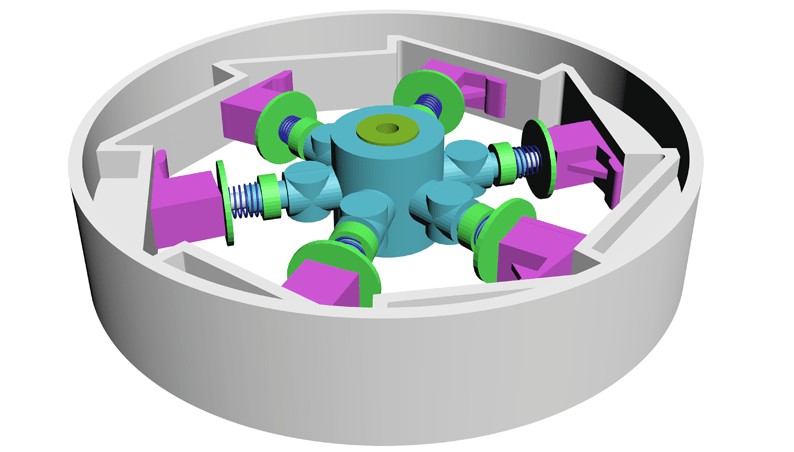
Here's a 3d model:-
gofund_me_perspective_v47foq.png

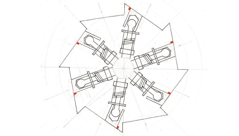
...and the forward pressure areas of such:-
gofund_me_power_areas_z8w6zf.png

I would like to share, and get this built. Do you think it would work?
...I'd love anyone to get involved
If you'd like to help, please reply with your thoughts
-I hope this is interesting,
if you would just like to comment on why or why this doesn't work,
I'd be curious to hear
Cheers
 
Replies continue below

Recommended for you

I haven't read everything in detail but... to me the critical flaw is where you say "there is no exhaust". With no exhaust there is no delta-P, no pressure differential. The entire chamber may be pressurized, but it doesn't "know" it is pressurized without some connection to the external environment. Pressure differential causes an unbalanced force, and that unbalanced force causes movement. With no pressure differential, no work can be done. Its one of the three inviolable laws of thermodynamics (exactly which one I'm not sure at the moment). Those laws weren't just made up by some scientist. They were "discovered" as pre-existing laws of physics that apply throughout the universe.
 
Air pressure acting on the red area in your drawing creates a force that will tend to push your rotor round in the direction you want.

Air pressure acting on the inward-facing surfaces of each piston assembly creates a force that will tend to make the slipper skate down the slope in the opposite direction, with a component resolved in the circumferential direction that's equal and opposite to the force you hope to exploit. This force is harder to picture but it's always going to be there, it's always going to be "equal and opposite" and it's what will always prevent the device from working.

So far as gauges go, you can stick the needles on so they read zero at any pressure that takes your fancy. 0 psia is a less popular choice than you might expect.
 
One side of this foot may indeed have more area, but this is irrelevant because the pressure on the other side of the foot is the same pressure, so there is no differential pressure.

No differential pressure, no force and no movement.

Remember - More details = better answers
Also: If you get a response it's polite to respond to it.
 
thank you for your assaying,
LittleInch
an example that I'd like to refer to is a pneumatic ram
with both ports connected to the same pressure source
the air pressure is the same,
but the piston head side will defeat the rod end side,
because the piston head has more area
The closed ram will open
This is meant to do that similarly
They have the same pressure, the one with more area has more movement force
zeusfaber
I am willing to accept that the forces forward and backward are in balance perfectly,
it's worth a try though imo -if the balance is equal, the scuffing feet may derive the straight plane as their axial path
if that's so, the redacted area means nothing. Only circumferentially plotting has area imbalance,
which may not be the trajectory/path/plot of the feet
...(edit) after a little further thought, it's probably that which would happen here
The wheel can not circumferentially govern, as the feet don't move to start with.
However, when the feet are mated with outer plane, they are pushed outwards,
not forwards, they can go backwards down the slope, and stop on the tooth.
As soon as the foot is lifted, it requires little force to put it over the next most internal point
...maybe it can go somehow- backwards to the original intent?
Jboggs
yes, this is the accepted convention, to maintain movement in an air powered system,
we need to apply relief/exhaust. I'm trying to think a way out of that
BrianPetersen
a spinning planet is nearly perpetually in motion,
as far as something like that existing

On Tuesday I'll get some steel and start,
also get a quote on the other printed parts soon
 
perhaps the rod moves because the surface area is different,
it has less pressure area
a pinhead at 30psi, has less motive force than a 1" bar at 30 psi.
perhaps
a large ram will defeat a small one(at the same pressure), because it's exposed to more area,
not because it has a different pressure

1" square bar equates to 30pounds, 1*1/2" square bar is 15 pounds

yes there is a transmission to a lower pressure in a ram

-so in the wheel form of this thing,
I can't send pressure forward or backward,
but I can send pressure inward and outward.
Geometry could turn this into rotation, if it pushed against an angle
 
Uncanny3 I am still perplexed where your design will develop a force imbalance. If the spokes and scuffing feet are not sealed/separated from each, and there will be closure plates on the sides of the exterior structure, but you have no exhaust, then your chamber will become an isostatic condition. What magic am I missing?
 
If that explanation of a ram was right you could put one on a submarine all by itself and the water pressure would push it just fine, no propeller required.

Call the Navy and explain how they no longer need a reactor for propulsion. I'll bet they put you right through.
 
Brian Malone,
Yes it is a state of dwelling atm,
as far as I can see it too.
The scuffing feet are meant to be governed into a circular condition,
but why would they be,
their mount is planar
and they feel only a linear, not circular pressure
if the circular line was actually the feet's path, it could work,
but the feet move along a straight plane, if they could, not circular

The intended principle is to imbalance area under pressure,
I cannot change the pressure without relief,
but maybe there is some way to manipulate area

I can only generate an inward and outward force,
against the outer wall and the hub,
not a backwards and forwards one at the moment
 
heya peeps,
please assay this one for a concept:-
Subducing_Ram_0_3_x6xbkk.png

the rams push outward forcing the main body up the races
when it has climbed as high as the travel allows,
we spin it upside down,
that will release it from the rails.
then the pressure in the chamber,
which is higher than the rams,
will push it closed again.
Then turn it right side up, and the head fall back to start orientation.
Now the redacted face allows it to start climbing again.

How do you like them apples?
 
Pressure is applied where (and when), and released where (and when)?

You can turn this thing into an air motor if you do the right things, although I don't see why it would be any more effective (or efficient) than any existing air motor using a crankshaft and pistons and timed valves, or an eccentric rotor and vanes, and it sure looks a whole lot more complicated, and I don't see how the motion profile turns into something useful (for example, rotation of a shaft). You (with a few omissions that we're trying to pin you down on) have (almost) explained the piston, but you haven't explained the cranknshaft, and connecting rod, and valves or porting.

What are you trying to accomplish, that a normal eccentric vane-rotor air motor doesn't do?
 
this is a proof of concept,
a motion that requires no more fuel than an original air head,
if the seals don't leak.
This isn't a motor design, just a proof of concept

pressure from the compressor is applied all the time,
but there is no exhaust/relief

To start a cycle the rams push open,
when they have travelled fully upwards,
the chamber is up-ended.
That allows the pressure in the chamber to close the rams,
as the rams have fallen away from the races
Then the chamber if flipped again,
and the shuttle falls back into a pushing state,
re-starting at the beginning of the cycle again and pushing upwards off the V races

I am trying to accomplish a motion of incredible efficiency,
a motor is a long way off in this concept drawing,
but I haven't seen the error in the motion it may create without relief
 
The sliding face of your triangle piece is exposed to chamber pressure throughout - both when it is in contact with the race and also when it is not. "Redaction" is not a real phenomenon (if it were, we'd have to find a way of making things without plain bearings, because they wouldn't work any more).

If chamber pressure is greater than ram pressure, the rams will retract and then just stay put.
 
Here's the 'order of operations' ==> What this is doing is possibly operating a potentially high power ram set,
using gravity as the switch for now
Operation_Cycle_png_sf7xg9.png


I don't mind it being called puffery,
it can't succeed, I am experimenting

If the faces against rigid things in pressure chambers do catch pressure, this will not work,
so I can believe there is no redaction, subducing or hiding faces in matings,
when I have seen it happen I guess. It made/makes sense to me
-there is atmosphere to bear pressure in a low tolerance mating?
 
If light-blue represents pressure and white represents absence (or less pressure) then the transition between frame 1 and frame 2 involves the pressurised fluid performing work between the cylinder block and the yellow things. Step 3 represents no work being done. Step 4 represents no longer any mechanical contact between the pistons and the yellow things, which presumably means the pistons have reached a mechanical travel limit imposed by something else not indicated in the illustrations which is fine. Step 4 does not happen because the yellow things are no longer in contact and cannot transmit any force; pushing the pistons in would requires mechanical work being put back in that precisely offsets that which was done between frame 1 and frame 2. Anything beyond that point is irrelevant because step 4 could not happen as shown.
 
"but there is no exhaust/relief"
Didn't we cover this already?

A couple more questions:
- What is "subducing"?
- What is a "redaction" in this context? I always thought it meant to black out selected words in a document.
 
@Uncanny3

I think you are missing some information on pneumatic cylinder construction. The two ports feed to either side of the piston. The rod is just a way to transmit the motion of the piston. If you apply pressure to both ports, the piston will not move.

Here is a cutaway of a cylinder. The image is courtesy of Tameson.com

Cylinder_ujfz3l.jpg
 
This closed system has frictional losses in the piston/ram seals and no outside connection to do work, so outside energy is expended to flip the system 180 degrees on some type of cycle. Energy that is not provided by the inside system. As 3DDave has noted, your mechanism is analogous to a sand timer. I am missing the goal of the experiment.
 
Status
Not open for further replies.
Back
Top