Continue to Site

Eng-Tips is the largest engineering community on the Internet

Intelligent Work Forums for Engineering Professionals

  • Congratulations KootK on being selected by the Eng-Tips community for having the most helpful posts in the forums last week. Way to Go!

Substation Design 5

Status
Not open for further replies.

SauravWest

Electrical
Dec 4, 2019
35
Dear sirs,

I want to design an intermediate substation which can transmit around 555 MVA.
Incoming double circuit 220 kV lines bring power. And outgoing 132 kV double ciruit lines take power.

1. Will single breaker double bus system be sufficient?
2. For high power, we use single phase autotf, so 6*92.5 MVA will suffice I think.
3. If Gas insulated substation, how equipment arrangements continue? I think it starts from lightning arrester, CVT and then?
4. PT can be kept one for each bus?

Please reply,

Sincerely,
 
Replies continue below

Recommended for you

Sorry to say that, it is my understanding that this site is just a forum to discuss tech issues but not a "DESIGN GUIDE".
 
Never understood the concept behind double bus single breaker. Sounds like four breaker rings would fit the bill.

I’ll see your silver lining and raise you two black clouds. - Protection Operations
 
The station configuration AIS or GIS is driven by the system reliability and somehow influenced by the regional engineering practice.
A double bus single breaker is common in the IEC marketplaces but less common in the ANSI región where ing bus is very popular.

See if the table below can help to make your decision in this matter.

Substation_Configuration_Reliability_u4okoq.jpg
 
@David: Not to worry, we can convert you :)

Advantage of SBDB is that you get the simplicity of straight bus with the ability take an entire bus out of service without having to shut down any elements. Additions, testing, relayig settings ect are relatively straight forward. Busbar protection and breaker failure is skipped in some countries since it is less essential than in multi breaker designs.

Down side is lots of linear space and of course a stuck breaker or busfault removes at least half the station from service.

@OP: This may help:

 
While a bus outage is occasionally needed, breaker maintenance should be much more common and DBSB does nothing to help that.

I’ll see your silver lining and raise you two black clouds. - Protection Operations
 
Davidbeach,

How doesn't it help with breaker maintenance? If you isolate a breaker, the associated line can be fed from the other bus. Unlike with ring bus, you could perform maintenance on multiple breakers at once and still maintain service.

Personally, I think it is an expensive design that is more about having a straight forward path for expansion than redundancy. You could just put in a long buses or extend the buses whenever more bays are needed and just plan that into the amount of space needed.
 
If you want the flexibility of taking out a whole bus go with BAAH and you also have the flexibility to work on one breaker in each of some of the bays at one time. If the implications of having a position out to do bus work are less onerous but you still want the flexibility to do breaker maintenance go ring. If you're just cheap go simple bus.

We have several older Main and Transfer (Main and Aux) installations so I'm familiar with that type of thing. Haven't missed the second main bus, don't like the aux breaker unless I can wire it's CTs directly into all of the position relays (it becomes a dual breaker solution with one CT or the other being used). Find BAAH to be about ideal, but they should be split with bus setionalizing breakers before they get to be nine bays long.

I’ll see your silver lining and raise you two black clouds. - Protection Operations
 
I agree- BAAH is actually ideal out of all the substation designs- the most reliability per acre of land.

I'd say the reason you haven't missed the second main bus is due to lines swapping outside the substation and/or down stream load serving substations having sources from more than one bulk substation. At least thats what I've noticed looking from above on Google Earth. Though once you head South of Washington State and Oregon, double busbar with breaker bypass becomes the norm in California for anything built in the early 2000s and prior. If the North had a more intensive, less looped network history probably would've favored SBDB.

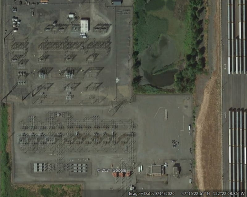
For example, I found this substation in Tacoma where the 115kv is M&T, but the mostly radial 57kv (?) is SBDB with bypass:

Clipboard01_xh1xuj.jpg


And yes, I get you! I never could figure out how to relay the transfer bus until I learned here about the 400 series SEL relays.

In the EU typically the transfer bus is found on 400kv lines that can not be taken out of service for very long, while at 11kv, 33kv, 66kv and 110-132kv the transfer bus is skipped since a long mid season outage is not of much issue.

@David: Do your old stations have breaker failure or BB protection? That is frequently skipped in developing countries since it makes little difference if you have it or not in M&T.
 
The lowest voltage in that picture is more than 100kV; might be SBDB, but the use of stain bus makes it difficult to see the connections. The higher voltage is a very typical M&T arrangement for that utility.

I’ll see your silver lining and raise you two black clouds. - Protection Operations
 
Yup, humbly the station does looks like strain bus to me. Now that you mention it that could very well be 115kv looking at the insulators from across the street in Google Street view, but ultimately you would know far better than me as I don't permanently reside on the West Coast of the United States. Now, as for Con Edison... :)

 
The other possibility typically employed on Medium Voltage systems is just to use a straight bus or sectionalized straight bus. Typically in that case, there are feeder ties located very close to the substation and the feeder ties can be used to allow breaker maintenance by tying the feeder you want to do breaker maintenance on to an adjacent circuit. This is how my local utility does it. It can also be done in the transmission world as well, however, each circuit needs to have this contingency in mind so that you can take the breaker out of service without severe negative consequences on the load flow or service to substations.

The primary disadvantage to this scheme is you may only be able to breaker maintenance during certain times of the year when loading is reduced on the circuits. The advantage is simplicity and savings on switchgear costs.

The conservative approach to the design is to utilize some type of double breaker design (Ring Bus, Breaker and a Half, Double Bus, Double Breaker), or doing a transfer bus. With medium voltage breakers in metalclad gear a cost effective way of doing this would be to do a transfer bus with essentially two breakers per feeder position, however, the second position is a spare "empty cubicle" position for a breaker to be racked in/out. In this way you aren't buying twice as many breakers but still have the level of redundancy for breaker maintenance. On transmission systems, typically motor operated switches are used, which you can see on Mbrooke's post above. That is a double bus, single breaker system with a transfer bus. All busses remain energized and in phase which reduces the arcing when the motor operated switches operate.

In some cases there is movement towards solid dielectric and SF6 switchgear for medium voltage equipment. I've seen claims that the breakers are maintenance free, however that comes from manufacturers claims which I don't always trust. With that maintenance free lifetime operation in mind, the switchgear can be greatly simplified, if it really is possible.

 
Another nice feature of the feeder ties located very close to the substation with a MTM straight bus is when upgrading the feeder breakers and / or relays (utility environment), with the feeder ties still in place you can bring in one feeder at a time to check the diff scheme and if there were an issue with the diff relays, you would not loose customer load.
 
The station in the upper half of the picture is 115 kV with strain bus. It was originally built as single breaker double bus with breaker bypass. Although this physical configuration theoretically can be operated half the load on each bus, operational realities meant that it was actually operated as main/transfer. Bus differential protection was a nightmare. This configuration has failure modes with moderate probabilities of complete substation blackout.

The 115 kV portion has been physically reconfigured into two separate buses with a bus tie between them (M-T-M). Planned maintenance outages to half the terminals are overall better reliability than accidental loss of the whole station.

David is correct that the stations in the lower half of the picture is 230 kV main/aux. The main bus has a bus sectionalizing breaker in the main bus.

kartracer087 -Neither portion of Mbrooke's photo has double bus single breaker with third transfer bus. In this region, 115 kV switches tend to be manually operated and 230 kV switches often have motor operators.

MBrooke- Using the bus tie breaker relaying with a transferred line terminal used to involve a huge auxiliary drum switch with a position for each line terminal. Depending on the line characteristics, the electromechanically bus tie relays would be adjusted for the specific line terminal being bypassed. In many cases, backup relaying did not include remote communications. It is slightly ironic that using 400 series relays has made using the bypass feature much easier, but the feature gets used less often since SF6 breaker require so much less maintenance than the old oil breakers.
 
Lots of approaches to how to switch in the substitution breaker. To a large extent they divide into two broad categories. The major regional transmission entity used a separate relay on the substitution breaker, which would need settings adjusted for each use. Allows the normal relays to be out of service when the normal breaker is out. Sounds like Bacon’s company is in that camp. We took a different approach and use a relay transfer switch to move the substitution breaker currents to the normal relays. An RTS per position, all sharing a single handle that can only be removed in the Normal position. Now with the 4xx relays the RTS just needs a few contacts to tell the relays which currents to use.

I’ll see your silver lining and raise you two black clouds. - Protection Operations
 
for a 11 kV, 16.2 MVA generator, breaker the rated current is: 850 Amps,what is sc current of breaker?
 
Bacon4Life said:
MBrooke- Using the bus tie breaker relaying with a transferred line terminal used to involve a huge auxiliary drum switch with a position for each line terminal. Depending on the line characteristics, the electromechanically bus tie relays would be adjusted for the specific line terminal being bypassed. In many cases, backup relaying did not include remote communications. It is slightly ironic that using 400 series relays has made using the bypass feature much easier, but the feature gets used less often since SF6 breaker require so much less maintenance than the old oil breakers.


True, though not having remote communications wasn't/isn't that big a deal- keep in mind some of these older stations outside the US did not have breaker failure or even busbar protection. Zone 2, Zone 3 and Zone 4 did all the protection. POTT vs no POTT was insignificant.

400 series relays are blessing, the transfer bus isn't going away anytime soon as a whole though it is becoming less common due to SF6 breakers as you say.
 
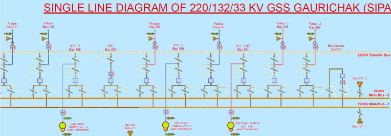
 https://files.engineering.com/getfile.aspx?folder=6fcf28d1-6b15-42f1-890d-669b403c3408&file=Gaurichak.pdf
The early/mid '90s combination of the SEL-321 and the SEL-279 (various versions) seemed to have spelled the sudden end of any design, in this region anyway, that relied on any kind of substitution breaker. There is, and always has been, a place for simple bus designs. But since it became possible to do a two breaker bay (ring or BAAH) with a pair of 321s and a 279 everything changed. We've had lots of new stations, or major rebuilds, since and not a single M&T, not even the thought of one. We'll push a ring to 6 positions, but anything more than that goes BAAH. Four or fewer may go ring or it may go simple bus. We also have six position rings where two of the positions are protected by SEL-487B relays; the initial build out is not the expected final build out. For new construction, I simply can't see how any sort of "single breaker" solution makes any sense today beyond a simple bus with a couple of line positions (breakers) and a couple of transformers (circuit switchers).

I’ll see your silver lining and raise you two black clouds. - Protection Operations
 
Status
Not open for further replies.

Part and Inventory Search

Sponsor