Eng-Tips is the largest engineering community on the Internet

Intelligent Work Forums for Engineering Professionals

Substation/HV grounding - Please let me know if my understanding is correct

EESS

Electrical
Sep 25, 2024
1
0
0
US

Hey y'all,

I am an entry level engineer trying to learn about substation/HV grounding, and it is quite difficult to learn so far. I was never taught grounding principals in school, so I am learning on my own - so please understand my knowledge on this is next to none. I have done some reading and watched some videos, and I want to understand the general idea and function behind grounding before further delving into detailed standards and design.

Ok, here is my understanding of grounding. Please tell what is correct, incorrect, and if you can add on anything please do so.

In summary. Grounding Grid is used to for/to protect:

People and Non-current carrying metallic objects/structures, such as poles, towers, equipment casing/chassis, switch handles, etc:
- If there is a LTG fault or any of these objects become energized, a voltage gradient is created, and all the grounded objects experience a rise in their ground potential (Right? And current will flow back into these grounded objects as well?). The ground grid acts as a return path if the source is grounded through the ground grid/earth. (Here's where my understanding becomes poor) The current returns to the neutral of the grounded source, where a relay can trip and isolate the fault? My understanding of this is poor, so a further explanation would really help!
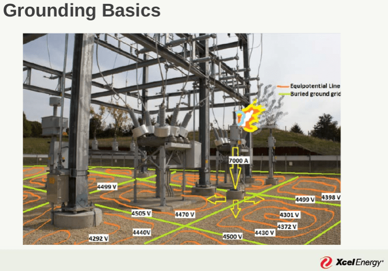
- If the ground voltage rises (GPR), this can also create a touch voltage as well as a step voltage. Can someone elaborate the idea behind designing the grounding grid such that these voltages are below the acceptable limit? How can we limit voltage gradients and touch potentials for humans?

Protecting current carrying equipment
- The neutrals of transformers (power, CT, PT's) must be grounded so that fault current can be directed to earth. When there is a GPR, these grounded neutrals experience a potential rise, which drives a current through them into ground. If they were not grounded, the LTG fault could fry them.
- I know that CT's aren't supposed to be grounded on both sides if I'm not mistaken -- can you please explain why that is?

Safety measures -
- Diverts static build up into ground
- Lightning arresters: Provide a direct path to ground in the case of a surge. Connected parallel with devices like transformers?. Once the clamping voltage is reached, it acts like a switch, diverting current to ground to just dissipate in the grid?


Please let me know if there's anything I'm missing, any explanations to my questions or incorrect explanations would be greatly appreciated. Thank you in advance!
 
Replies continue below

Recommended for you

1. Grounding Grid Purpose:
The primary function of a grounding grid is to protect people and non-current carrying metallic objects, such as poles, towers, equipment enclosures, and switch handles, by keeping the ground potential as close to zero as possible during fault conditions.

2. Fault Scenarios (Like a Lightning or LTG Fault):
If a fault occurs, like a lightning strike or a short circuit, the fault current can energize normally non-current carrying objects, creating dangerous voltage gradients.

Voltage Gradient & Ground Potential Rise (GPR): When current flows into the ground during a fault, a ground potential rise (GPR) occurs, meaning the potential of all objects connected to the grounding grid increases. Yes, you’re correct—current will flow through the grounding grid to find a return path, such as back to the neutral of the grounded source (e.g., transformer or generator).

Return Path & Neutral: The grounding grid provides a low-resistance path for fault currents to return to the neutral of the source (e.g., substation or transformer), which is also grounded. This creates a loop. When the fault current flows back through the neutral, a protective relay detects the fault and trips the breaker, isolating the faulty part of the system. The faster this happens, the less hazardous the fault becomes.

3. Touch and Step Voltage:
Touch Voltage: This occurs when a person touches an energized object and simultaneously has their feet on the ground. The potential difference between their hand (touching the energized object) and their feet creates a current through their body.

Step Voltage: This happens when a person’s feet are at different potentials because the ground they’re standing on has a voltage gradient (for example, near a fault).

4. Limiting Touch and Step Voltages:
To prevent injury from these voltages, the grounding grid is designed to keep the voltage difference between the ground and the object, or between two points on the ground, below a safe threshold.

Design techniques to limit dangerous voltages include:

Increasing the Size of the Grounding Grid: A larger grounding grid spreads the fault current over a wider area, reducing the voltage gradient at any given point.

Lowering Ground Resistance: By installing more conductors or rods, the resistance of the ground system is reduced, making it easier for fault current to flow safely back to the source.

Using Conductive Surface Layers: By adding materials like gravel or asphalt over the grid, step and touch voltages can be reduced because these materials have higher resistivity than soil, limiting current flow through a person’s body.

Careful Layout: The grid is designed to ensure that areas where people or equipment are located have controlled voltage levels, with conductors spaced closely in high-risk areas.

Summary:
The grounding grid protects people and equipment by providing a low-resistance path for fault currents.
It ensures that fault currents return to the source’s neutral (where the fault can be detected and isolated by relays).
The design minimizes touch and step voltages by limiting voltage gradients through effective grid layout and materials.
 
why current transformers (CTs) shouldn’t be grounded on both sides:

1. Avoiding Ground Loops:
What is a ground loop?
A ground loop occurs when both ends of the CT secondary circuit (the measuring circuit) are grounded, creating a closed loop through the ground. In such a loop, unwanted currents can circulate between the two grounding points.

Why is this a problem?
Ground loops introduce circulating currents that are not related to the current being measured by the CT. These extra currents cause:

Inaccurate Measurements: The CT is designed to accurately replicate the primary current in a proportional manner for metering or protection purposes. Ground loops can distort this signal, leading to incorrect readings.
Noise and Interference: Electrical noise and interference may be introduced into the CT secondary circuit, which can disrupt relay operation or metering functions. This can affect protection schemes or cause malfunctions in the system.
2. Safety Hazards:
Dangerous Voltage Buildup:
If both sides of the CT secondary are grounded and a fault or disturbance occurs, this can result in a potential difference between the two ground points. This can cause a buildup of high voltages on the primary side of the CT, leading to:
Insulation Breakdown: High voltage buildup may exceed the insulation rating of the CT, causing damage or failure of the CT.
Shock Hazard: The high voltage on the CT’s primary or secondary could pose a serious safety hazard to personnel working near the equipment.
3. Best Practice: Ground Only One Side:
Clear Ground Path: Grounding one side of the CT secondary circuit provides a stable, defined potential reference point. The common practice is to ground the secondary side at the relay or metering end. This ensures that the system operates safely and the CT provides an accurate current signal without interference from unwanted currents.

Prevents Parallel Ground Paths: By grounding only one side of the CT secondary, you avoid creating parallel ground paths, thus preventing ground loops and the issues they cause.

4. Impact on Differential Protection:
In certain protection schemes, like differential protection, having grounded CTs on both sides can interfere with accurate detection of faults. Proper grounding is crucial to ensuring the correct operation of protection systems and relays.

Summary:
Ground loops caused by grounding both sides of a CT secondary introduce unwanted circulating currents and measurement errors.
High voltage buildup can occur, posing risks to equipment and personnel.
Grounding only one side (usually at the relay or meter) ensures safe operation, accurate measurements, and prevents interference.
By following this practice, CTs function correctly and provide reliable protection and metering.
 
I agree with the idea of a single point grounding for local equipment-except for the bonding connections.
NEC Art. 250, it recommends -indeed-to proceed in such a way with grounding and bonding connections that the objectionable currents will be avoid. However, it is not so clear how to proceed.
On the other hand ,the shield, armor, and other metallic layer overlapping the medium and high voltage cables has to be grounded at both ends in order to avoid the transferred potentials. So, a cross-bonding of the shields and conductors permits both ends grounding.
There are a lot of standards- and studies-for grounding, as IEEE 80, IEEE 575, EPRI-EL-2000 and many others- and in IEC World also others as BS7430, EN-50522, ENA EG-1, CIGRE B3 and many others.
 
First off the best resource of this would be reading the IEEE Std 80, as it provides all the background information on the research and criteria used for HV substation grounding in many regions of the world.
Now to answer/clarify your understanding-

“People and Non-current carrying metallic objects/structures, such as poles, towers, equipment casing/chassis, switch handles, etc. “
YES, and to give a bit more clarity on the area of confusion. Imagine you have a 115kV generation serving a 115/12kV substation 100 miles away (far enough to be a remote earth distance). If you SLG(LTG) fault occurs on the substation 115 kV, the ground current path is through the ground grid, into the earth, and you would see another GPR occur at the 115 kV generation ground grid too. The relay’s are typically sensing the current that is going through the phase conductors (though there are neutral CT for sensing residual fault on the last few windings of a transformer). Just another note, you might have heard of ‘fault current split’, which is essentially is the current that doesn’t go through the faulted ground grid taking another path (shield/neutral wires when available). This is an area that many that understand grounding studies … don’t understand fault current split.
For personnel safety, the grounding system is doing two things at once. A low impedance grid makes for a lower GPR, but a low GPR can be 1, 5, or 10 kV etc. relative to the fault current availability of the bulk electric grid. The second thing the grid does is that it elevates the soil surface potential, so if you had a 5 kV GPR and the soil is 4.8kV, its only a 200V touch voltage. Typically larger ground grids have lower impedance, while dense mesh reduce the soil surface voltage gradient.

“Protecting current carrying equipment”
Our HV systems are typically insulated with air, which for HV systems can mean a lot of space. If you had an ungrounded system, then the space/insulation design would require to withstand L-L voltages, but solidly grounded reduces that insulation requirement. Note that you can still consider overvoltage/transient overvoltage issues. Additionally you can detect a significant fault current more easily with the traditional time overcurrent approaches.
“Safety measures –“
- “Diverts static build up into ground” (not sure I follow this, but maybe you are thinking of a large facility that might be impacted by the soil gradients that occur when a thunderstorm passes (green book has a right up on this)
“- Lightning arresters:” you can probably find a good resource from arrestor works

There is an introduction to grounding book, its only 20 or 30 pages that is essentially a sparknotes version of IEEE 80, but I think that can help clarify things. They also have a free grounding workshop and the next one is Nov 6 2024

Let me know if I missed something that you wanted clarified
 
I've never quite gotten my head around the concept of "GPR". Is GPR the voltage difference between equipment in substation and local earth, equipment to remote earth, or difference between local and remote earth.

If someone has a basic example, they can share to help solidify I'm sure that will clear things up for me. Thanks
 
Substation ground grids serve the same safety purpose as equipotental ground mats, reference thread238-166391. Reviewing the discussion regarding equipotental zones and equipotental safety mats may clarify some of the points being made above.

The linked presentation discusses "IEEE 80-2013 - IEEE Guide for Safety in AC Substation Grounding", and has some examples of remote faults in segmented power systems.

Substation Grounding Tutorial, Joe Gravelle, P.E., Eduardo Ramirez-Bettoni, P.E., Minnesota Power Systems Conference;Thursday, Nov. 9, 2017
Screenshot_from_2024-09-28_12-28-57_xjslcw.png

Screenshot_from_2024-09-28_12-31-22_euztkb.png
 
From one of my previous related posts:

"Grounding mats for people" will only be effective if the person in question is wearing conductive or 'non-dielectric' footwear, in other words WITHOUT the Greek letter Omega on it; I got by for many years of inspections and switching in high voltage switchyards [ including 500 kV ones ] until the company implemented a new policy stipulating that any field staff entering any switchyard were to be wearing dielectric footwear.

I quickly learned to hold my keys in one hand and ground myself against grounded apparatus before, for example, opening mechanism box doors with the other hand [ addition via edit ] ; with this technique any arcing occurred between the key and the apparatus, rather that between my fingertips and the apparatus - and trust me when I say your education in the use of this technique will progress very rapidly, with special reinforcement occurring every time a little blue arc zings your fingertips, followed by a brief presence of "blue air" in the vicinity of your mouth! bigsmile

CR

"As iron sharpens iron, so one person sharpens another." [Proverbs 27:17, NIV]
 
crshears,

You may avoid a little discomfort by wearing conductive footwear when touching control cabinets. If you are not standing on a ground mat and touching a grounded structure when a high voltage ground fault occurs, you may experience fibrillation and death if you aren't wearing dielectric footwear.

 
crshears- Dielectric footware decreases the risk of death from step/touch potential, but increases the occurrence of painful shocks due to the human body forming capacitive voltage divider between the energized conductor and the ground plane. Hopefully this doesn't digress too far from the original question.
 
Hi bacon, not much of a digression at all IMO; relates directly to the presence of step and touch potentials and the manifold facets of dealing with them.

I always wore dielectric footwear, and the key-in-hand technique soon became second nature for me; the first time I got "the zap," it took less than half a minute to reverse engineer from the empirical to the theory, and my adaptation was swift.

CR

"As iron sharpens iron, so one person sharpens another." [Proverbs 27:17, NIV]
 
Back
Top