Continue to Site

Eng-Tips is the largest engineering community on the Internet

Intelligent Work Forums for Engineering Professionals

  • Congratulations MintJulep on being selected by the Eng-Tips community for having the most helpful posts in the forums last week. Way to Go!

Substation sub sectionalizing

Status
Not open for further replies.

Mbrooke

Electrical
Nov 12, 2012
2,546
I am currently evaluating several 345kv and 138kv GIS substations and have most of it nailed down. One question I can't figure, what benefit is there to having midpoint busbar sectionalizing switches? My calculations show nothing is gained because they can actually reduce the availability of a busbar- however upon looking at manufacture literature and actual substations commissioned in Europe and Asia- half the time its common to have them.

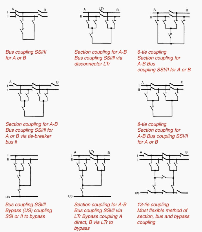
Here is an example:
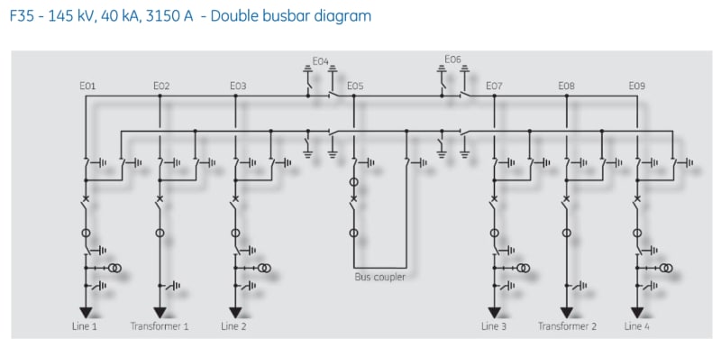
145kv_GIS_nebvn9.jpg


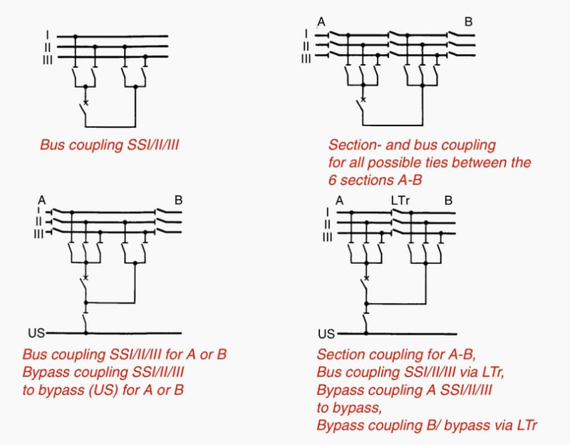
From an engineering guide...

DB1_yaln9z.jpg


TB1_lae3nr.jpg
 
Replies continue below

Recommended for you

Grounding (earthing) switches in GIS are used for:
. a) Provides extra safety to the maintenance personnel
. b) Ground capacitance (cables, transmission lines, etc.).

For additional details, see the following link: thread238-438187
 
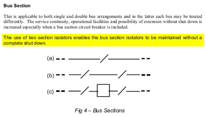
I am not referring to the earthing switches (which are essential in any GIS configuration), but actual disconnectors (isolators) subdividing the busbars themselves. Breaking the phases.


Some projects include them, others omit them- there seems to be no defining factor governing inclusion vs exclusion.


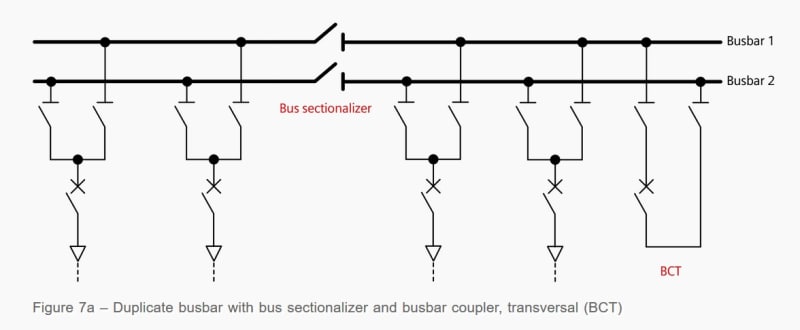
This might be a better diagram:
DB2_dlvlp6.jpg
 
I would make sure that every component can be adequately isolated for testing, maintenance and replacement. Work pratices in my state require an upstream disconnect(i.e the entire disconnect has to be deenergized in order to connect testing leads to one of the jaws).

In the first diagram you posted, how would you perform a millivolt drop resistance test or contact timing test on the bus coupler? Without E04 and E06, the entire substation would have to be shut down for testing the bus coupler.
 
The bus coupler has its own disconnects not labelled in the pic.
 
For straight bus I am in full agreement, but less so for double bus as the very reason for the double bus scheme is so you can place all the bays on the reserve bus while shutting down the main bus (for expansion or repair) without interrupting transformers or lines.
 
That might be a possible explanation- I do know in some cases elements are placed on different busses and the couplers are run normally open at major substations to reduce fault current, especially as the network grows in size.


Status
Not open for further replies.

Part and Inventory Search

Sponsor