Engineering1012
Chemical
New engineer here, this bounces off a question I posted a bit ago on recirc valves and got some help on. Bare with me on the information below.
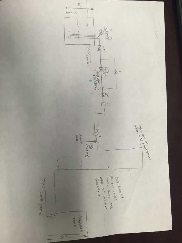
By design, there are three vertical pumps that pull waste from unit buildings and send it to are large atmospheric waste tank. They pump from a sloped sump that contains two settling chambers and a pumping chamber, separated by a weir. This helps the large particles that get through the initial strainer basket to settle, thus allowing the cleaner fluid to dump over into the pumping chamber. Out of the three pumps, one is a primary (constantly running) and another is on standby to switch on when the tank rises above 40%. The third serves as a backup along with an external diesel pump for emergency situations. The three vertical pumps feed into a common header where there is a throttling control valve. We've had numerous costly failures over the years before I got here, mostly dealing with failed bearings that cascade into impeller failures...etc.
I believe the root cause to be that the pumps are operating off their curve. Typical operation requires the primary pump to run at about 350 GPM which is around minimum flow for these pumps. However when they run in parallel due to rain...etc they need to produce 2000 GPM. Jist of this is, we have oversized pumps for normal operation.
I am working on a system curve and struggling in this area. Opening the throttle control valve 1000% the flow was 970 GPM with a discharge pressure reading of 22psig (~51ft). The entire system is tricky though and this is where I struggle.
1. So would that 22 psig on the discharge be my frictional losses in the system?
2. I can't really get an accurate measurement of my discharge tank level since it dumps into the bottom of a tank downhill over 1000 feet away. Not sure how to address my static head?
3. Would I be able to fit a parabola to the two points to fit the curve?
My preliminary options are.
-One small pump as primary, can be submersible or not however it is a diluted nitric acid harsh environment. (you may run into issues if needing to go parallel for more flow)
- VFD on the primary
- Larger recic line (Existing small one not sufficient, however large line may stir up debri in sumps and kill pumps)
All of these stem around first getting a reliable system curve. Any advice on this as well as my project in general would be much appreciated.
Thanks in advance.


