Continue to Site

Eng-Tips is the largest engineering community on the Internet

Intelligent Work Forums for Engineering Professionals

  • Congratulations KootK on being selected by the Eng-Tips community for having the most helpful posts in the forums last week. Way to Go!

Supply Side and Equipment Grounding Conductors in HV Substation

rockman7892

Electrical
Apr 7, 2008
1,156
I know that the NEC requires additional Equipment Ground Conductors (ECG's) to be run with any feeders between equipment and Supply Side Bonding Conductors (SSBJ) to be run between transformers of separately derived system and downstream equipment.

My question is in a HV substation environment where a ground grid is typically in place to carry fault current are either of these grounding methods required in addition to the ground grid.

For example between a substation transformer secondary that cable feeds over to an MV switchgear lineup, is an additional grounding conductor required to be ran along with secondary feeder cables?

If the switchgear inside of substation feeds to locations outside of substation are Equpment ground conductors required to be run with these feeders? Even if location of downstream equipment has ground grid that is interconnected to substation?
 
Replies continue below

Recommended for you

After looking into this a bit further I believe I've found some better understanding to my above questions.

From what I can see, anything inside of a HV substation yard that has a ground grid utilizes the ground grid for ground fault current between fault location and source in substation (or outside of substation). Therefore, on a 3-wire system or neutral grounded system there is not a need to run a separate ground conductor within the substation as the ground grid is intended to carry fault current flow.

For circuits such as feeders that leave the substation and its ground grid there needs to be a return path along with these cables for returning neutral or fault current to substation.

In a situation where there are no neutral loads (3-phase loads only) the requirement is to have a means to return ground fault current to substation. This can be accomplished in 3 different ways from what I understand:

1) Use of concentric shielded cable - Concentric neutral will be adequate for carrying fault current
2) Use of tape shield - Tape shield will only be adequate for carrying low level ground fault currents (impedance grounded systems) since tape shield has much less current carrying capacity than concentric neutral.
3) Use of separate ground conductor - A separate ground conductor is used primarily with a tape shield cable where the tape shield is not adequate for carrying ground fault current.

Appreciate anyone confirming my understanding of above or correcting me otherwise.

 
One other observation I had on several large scale renewable projects (BESS, Wind) is that on the 34.5kV collector system feeders from HV substation out Wind/BESS modules had both a concentric neutral as well as separate equipment ground conductor (typically #2AWG).

Have others found that to be common practice to run both concentric neutral and EGC for feeders? I'm assuming this would be to ensure lower path for fault return through cable grounds instead of earth? And ensure that combination of concentric neutral and EGC could handle available fault current?
 
Tape shields typically have low current carrying capacity, so I would always expect a separate neutral to be run with tape shields.

Concentric neutral can come in either full size or 1/3 size. Full size concentric neutrals are typical in single phase applications like underground residential, whereas 1/3 size neutrals are more typical for three phase loads.


According to IEEE Std 575™-2014 IEEE Guide for Bonding Shields and Sheaths of Single-Conductor Power Cables Rated 5 kV through 500 kV
6.3.3 Parallel ground continuity conductor
Since a single-point, bonded cable shield/sheath is grounded at one position only, it cannot, except in the case of a cable fault, carry any of the returning current. This being so, unless some parallel external conductor is available or is provided to serve as an alternative path, the return current can flow only by way of the ground itself. Because the resistivity of the ground is very high compared with that of good conductors, the return current is widely diffused through the ground and the mean effective depth of the current is hundreds of meters deep. Because the returning current path is significantly remote from the cable, the voltage induced along parallel conductors, including the cable shields/sheaths, tend to be very high.
That means then even in single end grounding shield case you need a parallel continuity conductor.
 
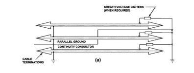
Further it is written here: To avoid circulating currents and losses in this conductor, it is preferable, when the power cables are not transposed, to transpose the parallel GCC as shown in Figure 2, using the methods described in Annex D, D.3.
 
According to IEEE Std 575™-2014 IEEE Guide for Bonding Shields and Sheaths of Single-Conductor Power Cables Rated 5 kV through 500 kV
6.3.3 Parallel ground continuity conductor
Since a single-point, bonded cable shield/sheath is grounded at one position only, it cannot, except in the case of a cable fault, carry any of the returning current. This being so, unless some parallel external conductor is available or is provided to serve as an alternative path, the return current can flow only by way of the ground itself. Because the resistivity of the ground is very high compared with that of good conductors, the return current is widely diffused through the ground and the mean effective depth of the current is hundreds of meters deep. Because the returning current path is significantly remote from the cable, the voltage induced along parallel conductors, including the cable shields/sheaths, tend to be very high.
That means then even in single end grounding shield case you need a parallel continuity conductor.
Thanks for reply. I was able to get my hands on IEEE Std 575 which has a lot of good info.

One thing I don't quite follow in the standard is how they define multiple single point grounding. I'm used to terminology of "grounded at one end" or "grounded at both ends" when it comes to discussion about grounding of MV cable shield.

The single point grounding makes sense but when the standard references multiple single point grounding, to me that is the same as grounding at both ends?

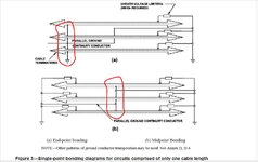
For example in the attachment from figure 3 of standard it references this as "single point grounding" but looking at figure it appears to be grounded at both ends? If so this appears to suggest that even with grounding at both ends a separate ground conductor is recommended.

Perhaps I'm missing something here as it relates to terminology and use of ground conductor? Single Point Grounding.JPG
 
One thing I don't quite follow in the standard is how they define multiple single point grounding. I'm used to terminology of "grounded at one end" or "grounded at both ends" when it comes to discussion about grounding of MV cable shield.

The single point grounding makes sense but when the standard references multiple single point grounding, to me that is the same as grounding at both ends?
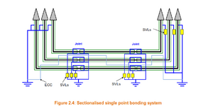
I believe multiple single-point grounding can also be called sectionalised single point bonding, please see Figure 2.4 from CIGRE TB 797 below:
1731006926877.png
For example in the attachment from figure 3 of standard it references this as "single point grounding" but looking at figure it appears to be grounded at both ends? If so this appears to suggest that even with grounding at both ends a separate ground conductor is recommended.
The sheath voltage limiter is essentially 'open', like a surge arrestor, so only one end of the cable is directly grounded. The sheath/shield is not normally grounded at the SVL end, unless there is a fault/transient. CIGRE TB 797 has some good explanations of the different cable bonding/grounding systems.
 
Last edited:
I agree with ema.
The shield is grounded on a single point- at one end or in the middle [in order to reduce 1/2 of the build-up voltage].
On the other end there are limiters only [surge arrestors]
They act only if the built-up voltage is too high.
The build-up voltage is the product of the current flowing in the main conductor by reactance between the main and shield.IEEE 575 shield grounding.jpg
 
Thanks for the responses, very helpful. No what I understand the figure and reading through the standard it appears that the standard only addresses single point bonding and cross bonding but not an application where the shield is simply bonded to ground at the end of each cable run.

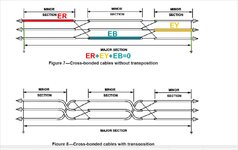
It appears that cross bonding is similar to having cable grounded at both ends only difference being the cross bonding between sections and not just bonding of each end of the same cable. Is this standard geared more towards utility applications and thus doesn't address a cable being bonded at both ends (wihtout cross bonding) as is typical in industrial applications?

Also is the only difference between single point bonding and multiple single point bonding, that multiple single point has the GCC cable and voltage limiters, but still only has shield directly bonded to ground at one end?

Cross Bonding.JPG
 
If there are 3 single core cables [three phases in flat arrangement] divided in major lengths and each major length divided in three identical -minor-lengths, then if each minor shield length is connected with other two phases the total build-up voltage per major length is zero-sum of three 120 degrees distanced vectors.
Then, you may connect each major cable length shield both ends to ground [no build-up voltage,IEEE 575 shield cross bonding.jpg no losses].
 
So it seems like cross bonding is essentially bonding at both ends which results in no build up voltage and also does not cause reduced cable ampacity due to circulating currents with shield bonded at both ends.

When cables are not sectionalized for cross bonding and are only a single run end-to-end then it seems like bonding at both ends of cable are only option for reducing voltage build up, but must account for circulating currents? In such a case is still standard to run a GCC along with shield?

Is there a reason why this standard does not discuss bonding at both ends for a single cable run?
 
What you are saying about cross bonding is correct, however, cross bonding can be difficult to implement due to geographical/space and cost constraints.

From my experience it is not standard to run a GCC as long as the sheath/shield has adequate fault performance.

Also, the introduction of the IEEE 575-2014 implies that 'special bonding techniques' are methods that reduce the derating of cables due to heat losses incurred via circulating current in the cable screens (which occurs in solidly bonded cables). So pretty much special bonding techniques is anything that is not single point bonded.
 
For both ends grounding case this standard recommends calculation of shield losses following IEC 60287-1 and then including this with main conductor losses and dielectric losses to recalculate the conductor ampacity following this IEC standard also.
There are already calculated tables in most of engineering handbook of almost each manufacturer and in standards as IEC 60502-2 [Annex B] for up to 30 kV cables.
 
In connection with the shield short-circuit withstand current is the standard ICEA P-45-482-1994 SHORT CIRCUIT PERFORMANCE OF METALLIC SHIELDS AND SHEATHS ON INSULATED CABLE
According with this standard, the allowable short-circuit current level in shield -or concentric neutral-may be different than the short circuit current in main conductor-even full concentric neutral, nevertheless, the start temperature is less but the maximum allowable temperature may be also less than conductor insulation. If the conductor insulation is XLPE or EPR the maximum temperature may be 250oC, but for jacket -if the material is thermoplastic-maximum temperature may be 200oC only.
 
What you are saying about cross bonding is correct, however, cross bonding can be difficult to implement due to geographical/space and cost constraints.

From my experience it is not standard to run a GCC as long as the sheath/shield has adequate fault performance.

Also, the introduction of the IEEE 575-2014 implies that 'special bonding techniques' are methods that reduce the derating of cables due to heat losses incurred via circulating current in the cable screens (which occurs in solidly bonded cables). So pretty much special bonding techniques is anything that is not single point bonded.
Sorry my last sentence was meant to say *solidly bonded not single point bonded.
 

Part and Inventory Search

Sponsor