Eng-Tips is the largest engineering community on the Internet

Intelligent Work Forums for Engineering Professionals

Support Lug FEA as per ASME Div 2 Part 5.

Status
Not open for further replies.

Sachin Poudel

Mechanical
Jun 26, 2021
13
0
0
NP
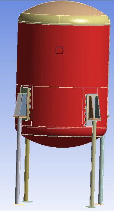
I did support lug FEA as per ASME Section VIII Div-2, Part 5, Elastic Stress Analysis Method (5.2.2). The model in analysis consists of Support Lug Assembly, Heads, Shell and fillet weld between Support Lug and Shell. The material properties of Shell and Support Lugs are as follows:
Allowable Stress: 16,025 @ 375 F
Yield Stress: 17,925 psi @ 375 F
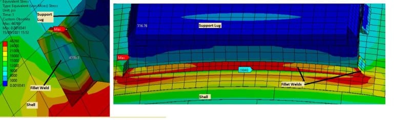
There is high stress in Weld. How should the stress in weld be interpreted as per Div-2 part 5? What are allowable stress in welds for Elastic Stress Analysis (Div-2, 5.2.2)?

I found that the stress in shell and welds increases as the position of support lug approaches shell-head junction. Can this be due to Secondary stress playing role near the shell-head junction? If so, can we treat the bending stress in weld as secondary stress?

Vessel_with_Support_Lug_n4qv6t.png
Stress_in_Lug_p1wew9.jpg
 
Replies continue below

Recommended for you

Sachin Poudel

Its may be late to answer your question. But please go through this thread. The explanation on thread is repeated here. The explanation is simple and may not be comprehensive and that is why you make sure to thoroughly understand the underlying fundamentals before making any assessment. Or in case of doubt use limit/elastic-plastic analysis route.

NRP99 said:
Imagine a long hollow cylinder with only internal pressure P closed at both ends by flat plates. Then the average stresses induced in mid section from ends will be free from bending and there will be only membrane stress. This membrane stress in the mid section can be classified as Primary membrane stress(Pm). Now towards the end section where the cylinder is closed by the flat plates, the expansion of cylindrical shell at the connection is restrained by the flat plates. So junction will impose loads in the shell section as well as flat plates. Hence there will be bending stresses near the junction in both end plates as well as shell section. Collectively the stresses at the connection(away from corner) of shell to end plate is called as primary + secondary stresses. Understand that Secondary stresses are introduced due to restraint and if we remove the restraint (in this case, remove end plates), there will be no secondary stresses. Hence secondary stresses are caused by restraint type of loading such as temperature loading and constraints.

Now imagine you drilled a hole in the same cylinder at mid section. There will be stress concentration due to hole since cylinder has to resist the same internal pressure with reduced cross section now. The average stresses near opening can be classified as the local primary membrane stress(PL) due to their local nature and local effect of hole(But make sure that these are really local and die out rapidly away from the hole). The total average membrane + Bending stresses are classified as primary+secondary stresses(away from hole edge). Here bending stresses are now introduced due to hole as restraint. At the edge of the hole there will be another component of stress apart from the primary and secondary i.e. peak component. This component comprises the most part of the total stress at that location and is mainly due to stress concentration effect. So at hole you have Primary+Secondary+Peak components of stress.

Note that these three stress categories are different components of total stress in section. There classification (you can say availability) will depend on the location in the cylinder. Primary stress-at mid section, Primary+Secondary stress-at shell to flat plate junction and Primary+Secondary+Peak stress-at hole.

Hope that this helps you in understanding the stress categorization which is bit tedious but very much logical.

I would use same stress classification as used in "pressure vessel" code which is conservative compare to structural code and involves "pressure vessel" in to it although the structural components are designed by structural codes like AISC/Eurocode. That way I am more compliant to the "pressure vessel" code.

Suggested reading references-
Search this forum for stress classification
ASME PTB-1 (Specifically read Annex A-CRITERIA OF THE ASME BOILER AND PRESSURE VESSELS CODE FOR DESIGN BY ANALYSIS IN SECTIONS III AND VIII, DIVISION 2)
 
Status
Not open for further replies.
Back
Top