Eng-Tips is the largest engineering community on the Internet

Intelligent Work Forums for Engineering Professionals

Support reaction distribution in plate with one bolt

Status
Not open for further replies.

muruep00

Civil/Environmental
Oct 16, 2023
26
0
1
DE
I have a rectangular steel plate with a bolt in the middle and pinned supports at each extreme.

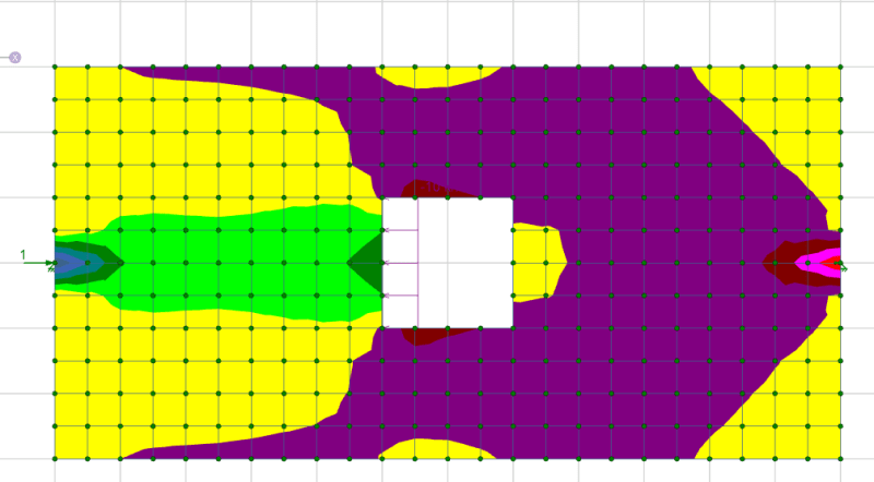
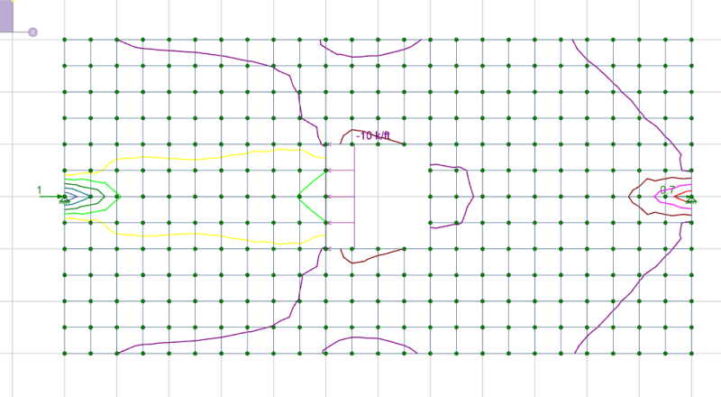
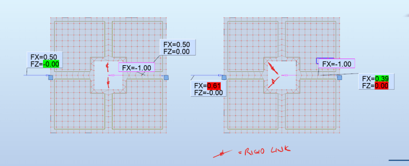
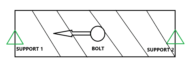
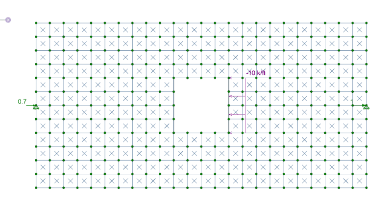
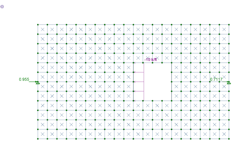
The bolt transmits a force to one side of the plate. Theoretically (following linear statics), both supports have the same reaction force value. But is this tru in reality? Doesnt large deformations + plastic deformations change the 50/50 reaction distribution? Which support gets more load? My intuition tells me that the compressed support 1 will have a greater reaction force than the tensioned support 2. Both supports are also bolts.

I attach a quick sketch of the problem:

pLATE_jrcqyf.png
 
Replies continue below

Recommended for you

The load path in your picture is more direct to the left support that is in-line with the bolt and the load will have to make its way around the top and bottom of the hole to the right side support. I think most people would ignore this unless you are building something more intricate. I would expect the size of the hole relative to the plate width to influence the deformation needed to get the load to the right side support.
 
muruep00 (Civil/Environmental) said:
My intuition tells me that the compressed support 1 will have a greater reaction force than the tensioned support 2.

Why do you think that? Is support 2 not an actual pin support but instead a roller? Is the bolt not actually in the middle of the span but closer to support 1?

If it is pin-pin and the bolt is in the middle, then you will get 1/2 of your plate in compression, and the other half in tension. The statics and mechanics of the situation appear to be straight forward.

Please note that is a "v" (as in Violin) not a "y".
 
WinelandV said:
Why do you think that? Is support 2 not an actual pin support but instead a roller? Is the bolt not actually in the middle of the span but closer to support 1?

If it is pin-pin and the bolt is in the middle, then you will get 1/2 of your plate in compression, and the other half in tension. The statics and mechanics of the situation appear to be straight forward.

Yes, I know very well the statics and linear theory.

But what happens in reality? Doesnt the bolt have plastic deformation on only one side? How do large deformations and nonlinear geometric analysis benefit one support over the other? Is there a nonlinear FEM example that proves it?
 
If you want reality, nothing is truly a pinned support, so the actual distribution of load will depend on the actual relative stiffness (fixity against lateral movement) of the 2 supports, and to a lesser degree the actual variations in the modulus of elasticity within the plate.
 
BridgeSmith said:
If you want reality, nothing is truly a pinned support, so the actual distribution of load will depend on the actual relative stiffness (fixity against lateral movement) of the 2 supports, and to a lesser degree the actual variations in the modulus of elasticity within the plate.

Both supports are also bolts.
 
whichever support has the lower gap will see the most load. One support will bear up before the other.

"Hoffen wir mal, dass alles gut geht !"
General Paulus, Nov 1942, outside Stalingrad after the launch of Operation Uranus.
 
"Real Life" will depend on a bunch of different things.
What is the bolt at support 1 bolting into vs at support 2? do they have the same relative stiffness? If one is more stiff than the other it is likely it will see more load.
What is the tolerance on the hole locations for the bolts at each support? Does one of them engage before the other? The one that engages first will (initially) see more load.
How large is the load - is it small where everything stays fully elastic or is it large enough that the first bolt engages due to hole placement tolerance but then that hole elongates due to localized plastic deformation (bolt plowing) which allows the load to redistribute more evenly to the two bolts.
So, based on the last scenario even in "real life" if all else is the same, just changing the load magnitude can result in the load being distributed differently.
 
Seems like the stiffer path might be to the left support by virtue of the applied load being closer to the left support, but as noted by others, there are a lot of variables here. If the plate is really thin, for example, I can see a scenario where the plate buckles under compression, resulting in the right support taking the majority of the load.

 
What is the load level vs the bearing yield strength of the plate?
What is the application and why are you worried about it?
What is the hole size/tolerance vs the bolt diameter?
 
What dauwerda typed is correct.

For other than high loads, it's probably nearly impossible to compute an accurate distribution of the load going left and right in that picture.

This reminds me of a paragraph in a set of mid-1960s Plastic Analysis notes that I got my hands on at some point. It stuck with me.

"More assumptions are required for elastic analysis than for plastic. Small fabrication errors, support settlements, residual stress, construction misfits, stress concentrations, deviations from assumed geometry and material properties are difficult to include in elastic analyses and often cannot be foreseen. No real hinges, simple supports, or fixed supports actually exist. Thus designing for fire first yield is pure fiction."
 
Here's what happens in reality.

1. One end of the plate has a hole drilled such that the edge of steel hits that bolt first.
2. That bolt will yield a bit and possibly go into the plastic range for a tiny bit because it is taking double the design load.
3. That causes strain hardening to make that side a bit stronger.
4. The bolt on the other end engages. Now both bolts are loaded the same.

Even if this is cyclical, the long-term deformations will equalize the loads overall.
 
"reality" has friction and a bizzillion other confounding variables

"Hoffen wir mal, dass alles gut geht !"
General Paulus, Nov 1942, outside Stalingrad after the launch of Operation Uranus.
 
This is what I was trying to say. Assuming a deformable steel plate and rigid point supports at each end, the load is more direct to the left support and the reaction will account for that. I believe this is what muruep00 was asking and without any other variables thrown in.

1_gahqoe.png
2_oucntc.png
 
haynewp, if you replace the pin at the right end with a horizontal roller, how far does that node move in the model? My guess is it's an extraordinarily small distance.

The next question is whether there's enough slop in the system for either end, or the bolt in the middle, to move that far without engaging and beginning to deform elastically.

In my quote above from the old Plastic Analysis course, that's the kind of thing they had in mind.
 
also, I`m wondering if more load goes to the left because the load is applied closer to the left. Do the results change if you a) apply the load the the right side of the opening, or b) reduce the length to the right side such that the load is centered between the supports?
 
where is the large square cut-out defined in the original problem ?

"Hoffen wir mal, dass alles gut geht !"
General Paulus, Nov 1942, outside Stalingrad after the launch of Operation Uranus.
 
271828 said:
haynewp, if you replace the pin at the right end with a horizontal roller, how far does that node move in the model? My guess is it's an extraordinarily small distance.
-0.0067 inch based on what I happened to throw in this model I made in 3 minutes.


Once20036 said:
also, I`m wondering if more load goes to the left because the load is applied closer to the left. Do the results change if you a) apply the load the the right side of the opening,


3_ojzzxq.png


Once20036 said:
b) reduce the length to the right side such that the load is centered between the supports?
Increases to the right slightly as expected, less length so increased stiffness.

5_mm04bk.png
4_mssf7j.png
 
haynewp said:
-0.0067 inch based on what I happened to throw in this model I made in 3 minutes.

That's what I'm talking about.

That displacement is microscopic. If there's 0.007 in. of slop in either the left or right end, then ALL of the force will go to the other end. Instead of 0.9798 kip on the left end, it might be 0.9798 + 0.6868, which is 70% higher than the elastic analysis calculates.

The smaller the parts, the worse this seems to be. That's one reason FEA for steel connection design stands the hairs up on the back of my neck.

Ultimate strength analysis methods like plastic design or yield line analysis have a lot better chance of being accurate. In most cases, I think we use elastic methods because our tools are set up for them, not because they represent an accurate calculation. I think our industry places too much faith in them.
 
Haynewp:

Your load is not centered so is more or less giving the same result as a standard mechanics of material formula would provide. For a concentrated axial load located anywhere on a span the fixed end reactions are:
Ri = P (a-L) / L
Rj = -P a / L

For your setup I just counted squares which gives a = 10 and L = 24
Ri = P (10-24) / 24 = -0.58334 P
Rj = -P (10) / 24 = -0.41667 P

Your model total P = 0.9798 + 0.6868 = 1.6666 * -1 (load pointed to the left)
Ri = 0.9723 (to the right) relative error of 0.765 %
Rj = 0.6944 (to the right) relative error of 1.1 %

Screenshot_2024-04-26_103418_xcdgqi.png
 
Status
Not open for further replies.
Back
Top