Continue to Site

Eng-Tips is the largest engineering community on the Internet

Intelligent Work Forums for Engineering Professionals

  • Congratulations KootK on being selected by the Eng-Tips community for having the most helpful posts in the forums last week. Way to Go!

Support Types and Their Reaction Forces 1

Status
Not open for further replies.

MatthewMansfield

Civil/Environmental
Aug 11, 2012
47
Hello all

Please dont shoot me down for asking this question as I know it maybe simple for most people.

I am trying to remove doubt from my mind regarding the 3 x types of supports and their reactions.

To me the types of support and their reaction forces are:-

Fixed Support = Vertical Reaction, Horizontal Reaction, Bending Moment Reaction.
Hinged Support = Vertical Reaction, Horizontal Reaction.
Roller Support = Vertical Reaction, Bending Moment Reaction.

To me the above supports can ONLY have those reaction forces - would this be correct?

The reason I ask is because someone told me that a roller support does NOT have a bending moment reaction and i was immediately thrown into confusion.

Can anyone confirm?

Thank you.

 
Replies continue below

Recommended for you

Thanks for the responses and your opinions. Yes, the horizontal load was drawn incorrectly. In order to generate the support reactions, it shall be located on the beam as member force.

image_xled62.png
 
Something horizontal, I suspect...

image_hfazqc.png


Rather than think climate change and the corona virus as science, think of it as the wrath of God. Feel any better?

-Dik
 
r13,

You have not responded to my suggestion that pin and roller supports are at the bottom of the beam, not at the neutral axis.

For a simple span beam with uniformly distributed load, the end rotations can easily be calculated. If the rotation at each end is θ, the total strain of the bottom fibre is 2yθ where y is the distance between the neutral axis and the bottom of beam. If a pin support is used at each end, the total strain must be zero.

I suggested a way you can check that with your software, but you have simply ignored the suggestion. You seem to be more interested in clouding the issue than seeking the truth.


BA
 
I don't know what exactly you don't understand, so no comment. I've suggested many times to get the free copy of Risa2D, so you can use it to carry out your suggestion. I don't think we can discuss in a civilized manner, why drag on!
 
r13,

I don't know why you can't discuss this in a civilized manner. And I don't need software to carry out my suggestion!

BA


r13 said:
We know in reality, secondary effect shall be included to obtain true reactions afford by the pin support, that is important in design of the connection. Also, in reality, for beam over multiple supports, imo, should be modelled as beam supported by multiple pin supports, unless there is clearly no physical horizontal restrain at the interface, which is rare.

With all due respect and in a civilized manner: [love]

What should be included in secondary effects? How about temperature change? Is that a secondary effect? If multiple pin supports are modelled, the beams cannot change in length, causing axial forces throughout the beam and horizontal reactions at some supports.

Continuous beams do not always have the same cross section in every span. Even when they do, placing pin supports at the bottom of a beam, instead of at the neutral axis, causes horizontal support reactions which alter moments and axial loads throughout the beam.

This can be avoided by using one pin support, and the rest roller supports. Alternatively, by using horizontal roller supports at every location and adding one vertical roller support anywhere to provide stability to the structure. That would be my recommendation, contrary to the red text in the above quote.

BA
 
Maybe I am looking things differently, or simply wrong. But I have no intention to lie, and mislead less experienced.

image_ccckgx.png
 

Exactly, BART...

Rather than think climate change and the corona virus as science, think of it as the wrath of God. Feel any better?

-Dik
 
r13, what are you trying to show. You have pin supports deflecting, rollers sitting still. It does not make sense at all.

Honestly unsure where you are trying to go with your argument, are you just taking the piss and winding everyone up on purpose by posting the incorrect information repeatedly? If so you should stop, it isn't adding to the original intent of the post.
 
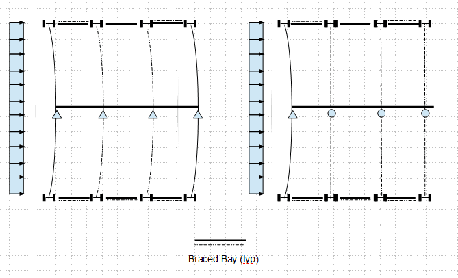
It was a view of a floor framing plan, with indicative support conditions at the beam, so not to waste my energy to draw cross section views. Please be more understanding before offering your harsh comment/opinion. I agree that this back and forth shall be stopped a long while ago, if not called repeatedly to respond. I will stop here then.
 
r13 said:
Maybe I am looking things differently, or simply wrong. But I have no intention to lie, and mislead less experienced.

Maybe you are looking at things differently. I do not believe, and do not suggest that you are intending to mislead anyone. However, I am not following your latest diagrams.

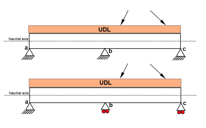
Below is a sketch of a two span continuous beam. The upper diagram has three pin supports located at the bottom of the beam. The lower diagram has one pin support and two rollers. The loading is the same for both diagrams, namely a UDL over both spans and a couple of sloping forces on the right hand span represented by sloping arrows.

An analysis of these beams will yield different results for shear, bending moment and axial load because the boundary conditions are different. We can discuss these differences in more detail if anyone wishes. The second diagram is the arrangement I suggested, but the location of the pin support can be moved to either point b or c if preferred.

image_yxke6r.png


BA
 
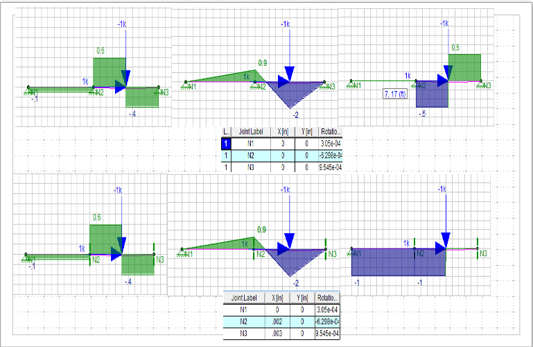
Interesting point, below is the two supporting schemes and results of the beam with inclined load (V=1, H=1). The upper beam is supported by 3 pins, the lower is pin-roller- roller. It seems the differences are the support reactions (horiz.), member axial forces, and lateral displacement and rotation.

image_mmzbfl.png
 
r13,

Your program is representing the beam as a single line with supports at the same level. In effect, that means your supports are at the neutral axis of the beam. You need to drop the pin and roller supports by half the beam depth to see a difference in the shear and moment diagrams. This means adding nodes N4, 5 and 6 at an elevation one foot (or half the beam height) below N1, 2 and 3 with three infinitely stiff vertical members fixed to the beam from N1 to N4, N2 to N5 and N3 to N6.

BA
 
BA,

Your suggestion/request is beyond the realm of elementary/general structural analysis, that considers all applied and resultant forces are acting on/about the centroid of the member; similarly, the support is located at the intercept of its axes and the centroid of the connected member, not the extreme fiber of the physical beam. You may try yourself the model as you suggested, and post the findings. I am eager to learn the difference, but don't know how to properly handle the modeling in a general purpose structural analysis program such as Risa2D. Sorry.

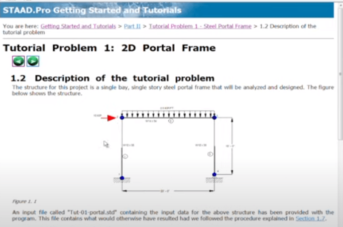
Note: There is a "member offset" commend in STAADPro, maybe that is something you are interested in. Haven't use the program for a longtime, so really can't provide information on how it works.
 
r13 said:
Your suggestion/request is beyond the realm of elementary/general structural analysis, that considers all applied and resultant forces are acting on/about the centroid of the member; similarly, the support is located at the intercept of its axes and the centroid of the connected member, not the extreme fiber of the physical beam. You may try yourself the model as you suggested, and post the findings. I am eager to learn the difference, but don't know how to properly handle the modeling in a general purpose structural analysis program such as Risa2D. Sorry.

The simplest frame is a single portal frame which can easily be analyzed by any 2D frame program. Multiple bay frames can also be analyzed by the same software.

When a single span beam is analyzed, it is usual to consider supports to be one pin and one roller. There is a good reason for that. If two pins are chosen as supports, the assumption of all forces acting at the centroid of the member cannot be achieved in a real structure because the pins are usually located at the bottom of the beam rather than at the neutral axis.

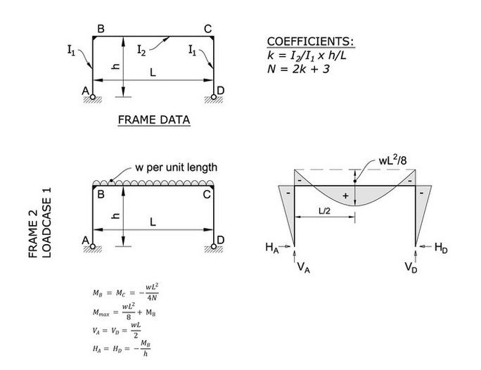
I am proposing to consider a single beam as a portal frame as shown below where the distance from the neutral axis down to the pin is 'h'. I will assume that I[sub]2[/sub]/I[sub]1[/sub] = 1, although it should be much smaller.

k = h/L and N = 2h/L + 3
Mb = Mc = -wL^2/4N = WL/4N where W = wL
Ha = Mb/h = WL/4hN

If L = 20'-0" and h = 1'-0",
then N = 5 and Mb = Mc = WL/(4*5) = WL/20
and Ha = WL/20*1 = W

The assumption of pin supports, using this method, produces significant end moments on the beam as well as a substantial axial compression.

If one of the pin supports is changed to a roller, the end moments and the horizontal force Ha both vanish.


r13 said:
Note: There is a "member offset" commend in STAADPro, maybe that is something you are interested in. Haven't use the program for a longtime, so really can't provide information on how it works.

That is interesting and may be another good approach to the problem. I do not have STAADPro, however and can't justify purchasing it under the present circumstances.

image_crglwe.png


BA
 
BA said:
...because the pins are usually located at the bottom of the beam rather than at the neutral axis.

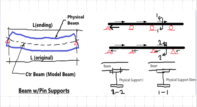
This is the mean difference of us. I do recognize your concern. In practice, we model according to member centroidal axis, and put support on the same level. If the perceived effect (I call it secondary effect) is large, we perform hand calculation (ie. M[sub]a[/sub] = H*d/2), or use member offset comment, and impose the load on the support. It is just something needs to be designed for, because in real structure the supports are most likely connected to the member above.

The structural models below show the typical way of modelling.

image_ueaye1.png


image_qh0cjc.png
 
FYI, here is the instruction of STAADPro "Member Offset Command". You can browse other topics too. Link
 
If, in the expression in my last post, I[sub]1[/sub] is taken as infinite:

then k = 0, N = 3
and Mb = Mc = WL/12 or wL[sup]2[/sup]/12 (a fully fixed end)
Ha = Mb/h = WL/12h

So the elevation of pin supports makes a huge difference in the result.
That is why we use pin and roller for a simple beam, rather than two pins.

BA
 
Status
Not open for further replies.

Part and Inventory Search

Sponsor