Continue to Site

Eng-Tips is the largest engineering community on the Internet

Intelligent Work Forums for Engineering Professionals

  • Congratulations cowski on being selected by the Eng-Tips community for having the most helpful posts in the forums last week. Way to Go!

Surface profile not normal to DRF

Status
Not open for further replies.

Hugh Man

Mechanical
Jun 7, 2018
6
Hi all,

I had a customer print come in recently with a surface profile callout that was very unusual for me and I wanted to run this by some people to see if this is allowed, or even makes sense to anyone else. I modeled up something simple to emulate the true parts datum structure and surface profile callout.

The part is centered on the axis of some ID, datum A. The rotation is controlled by B, and theoretical datum point C is the intersection of the axis with the top surface. I'm new with Fusion360 this is the best I could do to create that point. The surface profile controls the size and location of some features from apparent view detail A which is 60° from the top plane. I get that the perpendicular horizontal and vertical distances can be controlled relative to the axis and theo. point respectively from this view, I've just never seen a feature control frame that isn't looking normal to any of its datum controls.
Does this make sense to anyone else? Are there any examples you can share?
 
 https://files.engineering.com/getfile.aspx?folder=3cd98c52-4a2b-470a-8cde-470e947659d7&file=GDT_Test_v3.pdf
Replies continue below

Recommended for you

As long as you can describe the true profile you can apply a profile tolerance.

Excerpts from ASME Y14.5 - 2009

8.2 Profile
"...A true profile is a profile defined by basic radii, basic angular dimensions, undimensioned drawings, forumulas, or mathematical data, including design models."

1.3.16 Datum Feature
"A feature that is identified with either a datum feature symbol or a datum target symbol."

1.3.27 Feature
"A physical portion of a part such as a surface, pin, hole, or slot or its representation on drawings, models, or digital data files."

I'm not sure that a theoretical point can be a datum feature.
 
Hugh Man,

My primary objection to that drawing is datum[ ]C. Datums need to be attached to real features you can fixture to. They cannot be theoretical points. Perhaps you can get your customer to show a datum[ ]target. My interpretation of your datums is that A controls the position of your part in two axes, and B controls the rotation. C is needed to control the elevation, only.

The profile tolerance is completely legal and meaningful.

--
JHG
 
Angularity is a GD&T control that is not necessarily normal to the DRF. So profile can be thought of as just an extension of that idea to other, weird shapes.

John-Paul Belanger
Certified Sr. GD&T Professional
Geometric Learning Systems
 
I would absolutely agree with AndrewTT/drawoh - a theoretical point/axis/plane cannot have a datum reference directly applied, datum planes/axes/points are always derived from the actual features on a part. A datum target is also what came to mind.

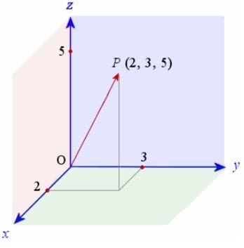
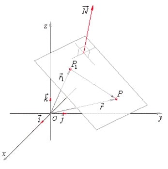
In regards to the being normal to the DRF theres no requirement that any feature and its FCF is normal to the DRF. In the example you are trying to create here your DRF will be 3 mutually orthogonal planes - where these 3 planes intersect is the origin of your DRF. This origin and three mutually orthogonal planes are where all dimensions need to be connected to and all measurements will be taken from this. If you think about it like the below, what you are doing is just setting up your x/y/z coordinate planes. These dimensions/features can be located anywhere in space as long as their relationship to the DRF (x/y/z coordinate planes) is fully defined. A single out of plane point/line/plane can be thought of like the below in terms of vectors and coordinates where its relationship is fully defined in relation to the 3 mutually orthogonal planes/origin. The same concept can be extrapolated to any other feature like a collection of points for your profile tolerance.

coordinates_vhs146.jpg


coordinates2_nfmrqt.jpg


As a side note - is the top edge of that surface actually a functional surface in the end use/assembly of the part?
 
Thanks all for the replies and insight, especially you chez. Thinking about it in terms of the coordinate system and a vector that cares about that cares about the one extra point of travel along the 3rd axis has really helped me understand this a bit better.

As for the theoretical point, datum target C, I didn't really even consider its legality at the time. its the only theo. datum target I've seen that's for sure but if we could simulate the intersection point I figured there's no harm in it. To answer your question chez, the top surface of the customer's drawing, which datum target C intersects, is the non-bearing surface of a bone plate. Its not a functional feature for end use.
 
Glad it could help! I remember having the same sort of question when I was first learning about datums, it never really sunk in until I thought about it like that - its sort of an obvious conclusion but it wasn't apparent to me until I made the connection.

Hugh Man said:
To answer your question chez, the top surface of the customer's drawing, which datum target C intersects, is the non-bearing surface of a bone plate. Its not a functional feature for end use.

I figured I would ask because it just looked a little strange, I had a feeling it was non-functional. I don't presume to tell you how to design your parts as there may be reasons why you may want to utilize certain features as datums even if they aren't functional/mating surfaces (someone else may have an example - I can't think of any except for maybe simplifying measurement or being utilized somehow in production of the part) however typically we want our datums to be functional or mating features.

Additionally something to keep in mind that is an extension of my original post referring to the datum planes since your part has a surface and features that are not orthogonal to each other, this should not limit you when setting up your datums if you want to utilize an inclined surface (or even other more complex geometry). All that information is in the standard, take a look at Fig. 4-7 and section 4.10.3 for a quick reference on inclined features.
 
Status
Not open for further replies.

Part and Inventory Search

Sponsor