Continue to Site

Eng-Tips is the largest engineering community on the Internet

Intelligent Work Forums for Engineering Professionals

  • Congratulations cowski on being selected by the Eng-Tips community for having the most helpful posts in the forums last week. Way to Go!

Surfacing IGES point clouds 2

Status
Not open for further replies.

Bi0mechanic

Bioengineer
Jan 6, 2006
17
I've been stuck with this forever. I have an IGES file of a 3D Surface scan with about 8000 point clouds. I need to somehow put a surface on the point clouds, and need to keep the cross section concentric. Any help would be truly appreciated.

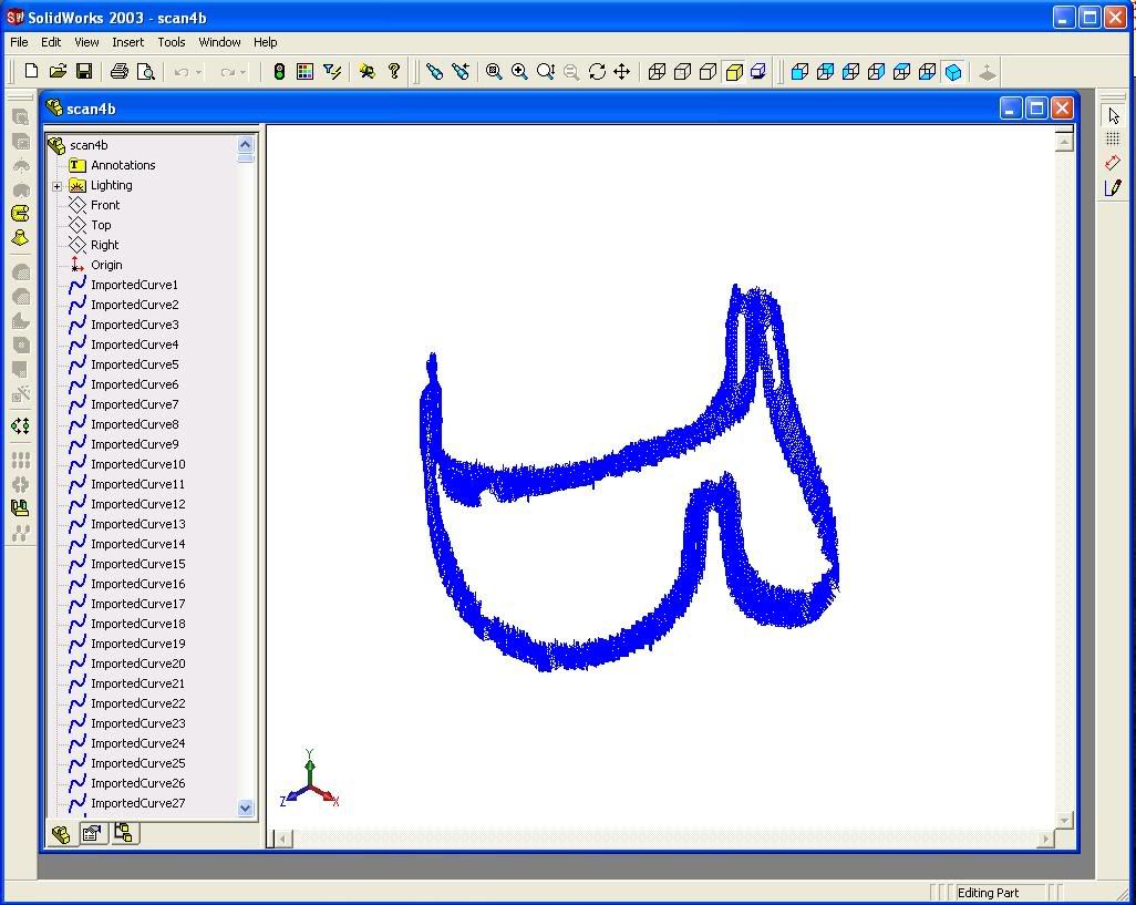
After the surface scan, I have a lot of point cloud data (about 8,000 points). Here is what it looks like in SolidWorks:
stentscan.jpg


The object is a heart valve stent, so imagine a cosine wave around a cylinder...

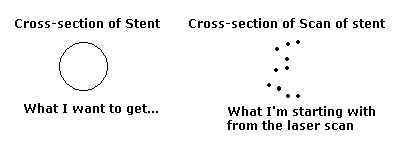
So the real object that we scanned has a circular cross section, and we are trying to recreate a 3-dimensional figure of the stent. If I look at the cross section, it looks like a bunch of zig zags if I connect the lines, but I need to somehow keep it concentric.
second.jpg
 
Replies continue below

Recommended for you

Hello Bio: I think this would be a good approach. 1)Import as Solid Body or Surface body under the options button when you import so you can snap to points 2) Use the 3D spline to draw a contiuous spline along the centroid of your "cross-section" 3) Sweep the circular cross section along the spline 4) Fight through the self intersection problem of the sweep in the small radius arcs by doing it in sections. If the "cross section" is of varying cross section you will have to loft it. Can you provide the point cloud data?

Tom
 
Hi Tom, thank you for your reply! I find it very difficult to do the 3D spline since the stent involves x,y, and z coordinates at every point, and SW does not allow for drawing with XYZ, only XY, ZY, and so forth.

As for the point cloud data, I have the IGES file. I can upload it sometime, but is that what you were looking for? Thanks so much.
 
Yes, post the point cloud data in IGES so I can try this thing. Thanks, Tom
 
The data looks incomplete and pretty noisy. I don't believe you can make anything useful directly from the data, even if you were to use something meant for that type of work such as Geomagic. Since you seem to have information about the shape anyway, I think you'd be best just to model it directly in SW, using the data as kind of a "ballpark" approximation check for size and position. Working with this kind of data is extremely tedious in SW.

To make the shape in SW, either projected curves or a spline on a cylindrical surface would be my approach. Projected curves would be easier to work with.

Good luck.
 
My thoughts exactly. The problem with this is that if I just spline and sweep with a measured diameter, would I be able to use this CAD for FEA? The main criteria is that we capture the 3D shape of it, and then we are able to use this CAD to apply finite element analysis.
 
Hey Peter, I have started working on the design and would like to know the diameter of the cross section. Is the wire used basically a continuous loop that is bent into the 3 sided sine wave? Do you have a photo you can post?
Thanks, Tom
 
Wow, I didn't know you were going to work on it! Well for the diameter, I didn't have a caliper with me, so I could measure it. However, I think 1 mm is a safe estimate...more like 0.95 mm. How are you creating the CAD drawing?

As for the photo, I cannot seem to get a copy of the picture, but if you go to this animation ( and advance to about 39 seconds into the clip, then you should be able to see it. I tried print screen, but it wouldn't work for some reason. Thank you so much.

-Peter
 
Your only hope in SW is to use the point import macro, and then to find a way to use the points to generate a surface. Go here to get it.


Convert your .igs file to a tab delimited text file with the xyz data. This is your only hope to create something in solidworks, but unordered scan data is very hard to work with.

What you really need to do is use a reverse engineering app that will clean up your noisey data, then triangulate a surface from the data. You can then use this polygon model for FEA, and if you have the right package you can surface the triangles to create a NURBS or parametric CAD model. Look up Rapid Form or Raindrop or CopyCad or 3d Reshaper to name a few. This stuff gets expensive.

If you post your data I'll take a look at it and give you an example of going from points to polys to nurbs with my tools.

RFUS
 
Hi RFUS, thank you for your reply! I actually posted the file in the link (yousendit.com link) a few posts before. I tried looking for a iges converter to the xyz data, but I can't seem to find a program that does that or have access to one. Thanks again!

-Peter
 
Here is a tab delim of your file, i called it Scan4btabdelim.zip. Units are mm.

Mooload wasn't working so its on this paininthebut site. keep going in till you get it to download... hit the one below where it wants you to pay a buck, and then save target as, then wait a while and it will come.

Run the macro I pointed you towards on this file. Now, if you wanted to surface this in SW, you would have to do this:

Close the 3d sketch. You have to go and 'insert curve through reference points' by selecting the points in each scan line. Use the point selection filter with view orientations. This will take a while. Then create a lofted surface using the curves.

But...You want to sweep a circle around this so now at least you have these points to use as ref geomerty to go in and create a curve around this thing.

If you wanted to have a model for FEA you would need to export your final model as STl which will give you a triangle network or faceted model.

During lunch, I tried triangulating and using and auto surface on this data and its pretty rough.

RFUS
 
Hi rfus, when I run the macros program, it keeps giving me an error saying that there is an invalid character in the code. I'm not sure of how how to fix this.

However, since you tested that data, and it came out pretty rough, that is exactly what we can't use. I'm going to try to rescan the object again, and take some good pictures of it.

Sweeping the circle around those reference points is exactly what I need to do, but it seems like it'll be more difficult than I ever anticipated. Is there any other way to sweep the circle around? This project is hopeless. Thanks.

-Peter
 
Peter, what is the trick to posting an image on this forum like you did? I have a model of the stent wire and want to post an image of it.

I don't understand the instructions on this website.

Thanks,

Tom
 
How to post an image ... faq559-1100

[cheers]
Helpful SW websites FAQ559-520
How to get answers to your SW questions FAQ559-1091
 
Yeah I tried looking around this forum and have been conducting several searches regarding this, but nothing addressed this specific problem. Thanks for the suggestion though!

-Peter
 
If you do this often, you might want to consider buying software. There are a variety of reverse engineering software packages that are tailor made to handle large size point clouds data from laser scans and construct various surfaces from them.

Pricewise on the low end, you have Rainbows's Geomagic, on the mid to high end, you have Innovmetric's Polyworks, on the high end you have Imageware made by UG (I think). And that is just scratching the surface. They will not be parametric in solidworks, although importing from such software should not be a problem for Solidworks. Geomagic is usually the easiest to use, and Imageware is usally the most powerful.

 
Can I make the imageshack linked image show up in the forum or do I have to use a web server as you say in your FAQ? Thanks.
 
Status
Not open for further replies.

Part and Inventory Search

Sponsor