Continue to Site

Eng-Tips is the largest engineering community on the Internet

Intelligent Work Forums for Engineering Professionals

  • Congratulations cowski on being selected by the Eng-Tips community for having the most helpful posts in the forums last week. Way to Go!

Surfacing IGES point clouds 2

Status
Not open for further replies.

Bi0mechanic

Bioengineer
Jan 6, 2006
17
I've been stuck with this forever. I have an IGES file of a 3D Surface scan with about 8000 point clouds. I need to somehow put a surface on the point clouds, and need to keep the cross section concentric. Any help would be truly appreciated.

After the surface scan, I have a lot of point cloud data (about 8,000 points). Here is what it looks like in SolidWorks:
stentscan.jpg


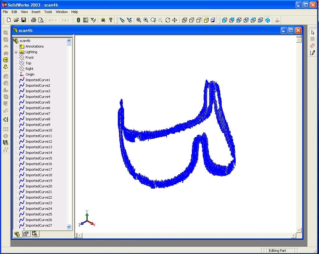
The object is a heart valve stent, so imagine a cosine wave around a cylinder...

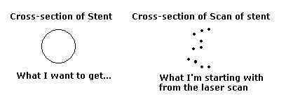
So the real object that we scanned has a circular cross section, and we are trying to recreate a 3-dimensional figure of the stent. If I look at the cross section, it looks like a bunch of zig zags if I connect the lines, but I need to somehow keep it concentric.

second.jpg
 
Replies continue below

Recommended for you

You could make it show up in the forum, but what you have done is better. It takes up less bandwidth, doesn't mess up the page size (like the first one did because it was too big), helps the page load faster & gives people the choice of whether they view the image or not.

[cheers]
Helpful SW websites FAQ559-520
How to get answers to your SW questions FAQ559-1091
 
Hello Tom, wow, that looks amazing. If I can remember the stent correctly, that is exactly how it looks like. How did you do that? That looks great! Did you use that IGES file or did you start from scratch? Thanks!!

-Peter
 
Peter- I snapped a spline to points in the messy point cloud following roughly the center of the cross section to make a "U" shaped spline. I then lofted it along its full length. Looking at the part and the point cloud you could see that the shape is somewhat distorted so I cut the "U" in half and mirrored it so it would be symmetrical. I then patterned that every 120 degrees. Then I had to add the little hairpin turn to the tops of the three "U" shaped pieces by using lofts. I think the only critical thing about the FEA is getting the proper radius for the 3 small hairpin turns at the top. Because the ratio of the diameter to the overall length of the wire I think the larger radii will not see much stress.
 
Wow, I can't even comprehend what you did in SW. Given that I have only had a few sessions of SW experience, I don't know if I can repeat exactly what you did. Would it be possible if you upload that file somehow? Thank you so much for your help!

-Peter
 
I have been trying to clean up some rough edges on it. I will try and send it tomorrow. -Tom
 
tommy104 ... any particular reason why you used loft instead of sweep?

[cheers]
Helpful SW websites FAQ559-520
How to get answers to your SW questions FAQ559-1091
 
Yeah. I've never used loft before. I always thought you would draw the 3d spline through the center, set the diameter, and sweep through the path?
 
I actually used sweep to do most of the wire so I told you wrong for the first bit of it - sorry. I used loft to make the smaller radius areas for no particular reason. I realize loft is more for varying cross sections. I have just gotten into habit of using loft more because I want to learn the new 2006 features. - Tom
 
Peter do you have Solidworks 2006? Otherwise you will not be able to look at the part model. If you need it to do analysis I can export it to step or iges. -Tom
 
Hi Tom, the most updated version of SW I have is 2004.5. Is it possible to send it as an IGES file, and I'll open it in SW 2004.5, and then save it as a STL file for FEA with Nastran/Patran? Thanks!

-Peter
 
Hi Tom, I tried to spline through the center, but I'm having trouble following the circular dimension. How did you go about doing that portion?
 
Peter- I snapped a spline to points in the messy point cloud following roughly the center of the cross section as you follow along it lengthwise. There is no circular "cross section" because the laser apparently did not rotate all around the part and do a good job. - Tom
 
How Do I Make Files Available For Download? ... No Emails Required faq559-1177

[cheers]
Helpful SW websites FAQ559-520
How to get answers to your SW questions FAQ559-1091
 
Hi Tom, I tried downloading the file, but it has nothing inside. I checked the file size, and it says 0 bytes on the mooload webpage. Is there someway to upload it again? Sorry for the hassle!

-Peter
 
Peter - I downloaded from that site this morning to check it and it worked. I just tried it from home and now it does not work. I will put it up again tomorrow. - Tom
 
Hi Tom, thank you so much for the files! I have a quick question regarding the files. How would I go about changing the diameter of the stent? Thanks!

-Peter
 
Status
Not open for further replies.

Part and Inventory Search

Sponsor