Eng-Tips is the largest engineering community on the Internet

Intelligent Work Forums for Engineering Professionals

Surge Arresters for Plug-in type GSUs

Status
Not open for further replies.

basilasq

Electrical
Jul 8, 2011
12
0
0
CA
Hi Everyone,

I have a Generator Step Up (GSU) Transformer with the HV side at 240kV. The high side terminations are via 'plug-in' bushings that only allow for termination of a 240kV power cable.
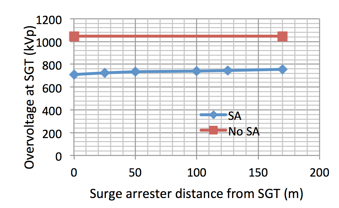
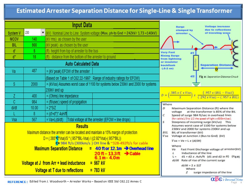
My concern is with placement of a surge arrester for Transformer protection. In a standard air bushing configuration, the Surge Arresters are located right next to the transformer bushing and within the required separation distance (calculated per IEEE C62.22). However, in this configuration, the closest surge arrester will be about 30m away where the 240kV cable terminates on a transmission line receiving structure. Per my calcs using IEEE C62.22 (App C), max allowable separation is about 20m.
My query is whether a 'internal' type surge arrester can be installed directly into the transformer and right next to the terminations? Has anyone had any experience with such installations? So far we have not received a positive reply from the GSU manufacturer.
 
Replies continue below

Recommended for you

Plug-in type bushing manufacturers have a model for connecting surge arrester near to bushing. Contact them eg:piffster. Not sure whether available for 220 kV.

But why the cable termination stopped 30 meters away? I would recommend conventional Air to oil RIP ( resin impregnated paper dry type)bushings for transformer and an outdoor cable pothead for cable termination as near to transformer as possible + an arrester on the jumper connection between the cable pot head and transformer bushing.

In one case the transformer was connected to 220 KV GIS through a short cable as there was a road between the transformer and GIS. So an oil filled cable box was provided on transformer. No arrester at transformer end. GIS disconnect switching produced surges and the cable amplified it causing failure of pothead or oil- oil bushing used in transformer; oil filled cable box exploded causing a transformer fire, transformer was entirely gutted.
 
Thanks very much prc for your response.

I have dealt with Pffister before and will request them for a solution.

The reason for using this configuration is that existing transformers are being re-deployed to this site. The manufacturer quoted cost for changing out the terminations to traditional air bushings was absolutely impractical for this project.

When you say 'cable amplified it', what do you mean? I was trying to look through IEEE C62.22 about how surge behavior would differ in power cables (vs. bare overhead conductor) but could not find anything.
 
Hi all,

Unfortunately, the Pfisterer plug-in surge arrester is only available up to 145kV.

Check with one of the surge arrester manufacturers to see if they can accommodate an SF6 encapsulate arrester with the HV cable plug-in module.

Below is an illustration with a possible solution suggested to be discussed with the equipment manufacturers.
Surge_Arrester_SF6_Encapsulated_sf7mnh.jpg
 
Thanks cuky2000
240kV solutions (such as the one you shared) are difficult to get per the vendor but they are looking into options.
 
Basilasq

It recognized that retrofitting an encapsulated surge arrester in an existing power transformer is a very challenging task.
Will be prudent to consult with other manufacturers such as ABB or Siemens for solution since they manufacture Transformer and other encapsulated modules using a different approach than Phisterer.

Good luck.
 
Basilasque-when a surge travels through a short length of cable it can get amplified at receiving end.

Cuky- what you have shown is arrester inside SF-6 duct. As I understand,in this case, there is no GIS involved and no gas filled cable box at transformer end. But plug-in type bushing makers have another adaption wherein arrester is incorporated as integral part of plug in bushing.I was with ABB transformers for more than 20 years,till last year. To my knowledge, we were not making plug- in type bushings.
 
Hi pro,
Considering the Pfisterer plug-in SA is not an option for 230 kV and the difficulties with the SF6 encapsulated. Convert he transformer with outdoor bushing with open air SA do not appears to be the optimal alternative.
Does anyone see a suitable option or suggestion?
 
1)This is an existing transformer with 220 kV plug in bushings.

2)It is said cable is terminated 30 meters away from transformer on a transmission line structure. Then how is the connection for this 30 meters? It has to be by cable as the transformer terminal is plug in type bushing.

3)If (2)is correct, then there will be an overhead junction 30 meters away with two outdoor cable pot heads and SA in between. If you select an arrester with lower residual voltage probably you may get sufficient safety margin for transformer. Suggest to get professional help.

4)If(3)gives not acceptable result, check possibility of shifting cable joint location nearer to transformer or get confirmation from plug in type bushing vendor whether he can supply suitable L connection to put SA.
 
Hey everyone,
Great discussion going on. Some more updates....
The transformer manufacturer (Siemens) confirmed that mounting arresters next to the bushing is not an option unfortunately. They also confirmed that the plug-in bushings are ABB.
The configuration is..... GSU HV bushing -> 25-30m of 230kV cable -> air termination -> transmission line H-frame. The line is a short length of about 2-3 km to a nearby substation. The transformer would be susceptible to lightning strikes on this line.
I am looking for arresters with low residual voltage that would meet the TOV and MCOV characteristics, but it is a challenge. Being in Canada we follow both CSA (IEC) and IEEE. IEEE C62.22 is more conservative for separation distance calcs as it used FOV (0.5us) characteristics. CSA C71 (IEC 60071) is more relaxed in this regard.
 
prc

I am interested in learning more about this statement:
"when a surge travels through a short length of cable it can get amplified at receiving end"

Does any standard quantify this? Don't think IEEE C62.22 takes this into account for separation distance calcs. Any more insight would be greatly appreciated
 
No, traveling surge magnitude tends to decrease with the cable length.
[sub]The amplification only happens at the discontinuity where the incident and reflecting wave may reach up to twice the surge.[/sub]
The example below despite the Overvoltage magnitude recorded at the transformer versus XLPE cable length
[sub]
Screen-Shot-2018-05-04-at-15.27.29.png
[/sub]

 
Yes, both the IEEE Std C62.22 (see annex C) and the IEC Std 60071

Max. Protective Distance:
a) IEC STD: [highlight #FCE94F]L = (v/2S)x(LIWV/K[sub]s[/sub]–U[sub]res[/sub])[/highlight]
[sub]Where: v=surge speed (300km/s for OH line & 1/3 to 1/2 for cable); S= max. steepness of the rise of an overvoltage wave;LIWV=lightning impulse withstand voltage;K[sub]s[/sub]= Safety factor for insulation(1.15 outdoor & 1.05 Indoor) U[sub]res[/sub] = arresters residual voltage. [/sub]
b) IEEE Std C62.22: See example with approx calc of the protective distance.
Surge_Arrester_Separation_Distance_Calc_-_1_line_1_Transformer_xsyfry.jpg
 
Clause 6.3.4.1 of IEC 60099-5-2018:
6.3.4.1 Overvoltage protection of cables
The essential difference between the electrical parameters of overhead lines and cables is the
surge impedance and the velocity of the travelling wave. Values for overhead single conductor
lines are in the range of 300 to 450 Ω and for cables in the range of 20 to 60 Ω. First of all,
this difference causes a remarkable reduction of an incoming overvoltage as soon as the
travelling wave enters the cable. The reduced voltage wave travels through the cable and it is
reflected at the cable end, so that the voltage is there nearly doubled. Subsequently the wave
returns to the cable entrance and is there once more reflected, etc. In this way the
overvoltage in the cable is built up to a theoretical maximum of two times the overvoltage on
the overhead line. This maximum overvoltage peak is depending on the cable length, so for a
short cable of just tens of meters the maximum overvoltage may reach close to the theoretical
value and the longer the cable is the lower the maximum overvoltage will be.

basilasq, then you may ask what is wrong with longer cable length? It is for better. Please note Annexure C calculation in C62.22-2009 is not valid for cable connections(See clause 5.2.3.4.2)
 
Now let us consider why it is suggested to reduce the distance between SA and equipment terminal. When SA discharges, a huge current flows to ground through the down lead from SA to ground. Consider the rectangle between this path + transformer tank surface as opposite sides and the connection lead between SA terminal + ground as opposite sides. This is the flux window from surge current that induces a voltage on tank surface that adds to protective level of SA.

So solution in your case: if the cable is with metallic sheath, at SA end, connect the down ward lead from SA to this sheath. At receiving end, connect this to tank earth. Otherwise run a grounding lead along with cable to achieve this. Net target is to reduce the area of rectangle as explained in above para. Rectangle between cable, grounding lead.
 

I do believe that the protective distance for the proposed case is a lot shorter than 50m(154 ft) and to achieve reasonable protection, surge arresters are needed near the transformer and at the junction of the UG and OH line.

Notice that the MCOV of the SA should be convenient to size not to exceed the max. phase-to-ground voltage (~140kV)


Status
Not open for further replies.
Back
Top