Continue to Site

Eng-Tips is the largest engineering community on the Internet

Intelligent Work Forums for Engineering Professionals

  • Congratulations KootK on being selected by the Eng-Tips community for having the most helpful posts in the forums last week. Way to Go!

Suspension Bridge cable tension verification; manual vs structural analysis model

Status
Not open for further replies.

SatoshiNakamoto09

Structural
Sep 2, 2014
25
Hello, let me know if I am posting in the right thread topic.

Should I confidently say that my structural model is correct? since I am getting the exact Tension cable by manual computation and structural analysis model result
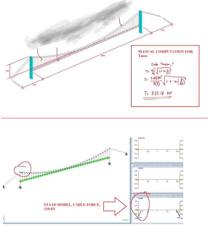
cable_pynnp8.png
 
Replies continue below

Recommended for you

Both methods have a bunch of assumptions built in. Neither or both might match reality.
 

Why? What do you think will be the most appropriate method of analysis ?

Is it because it is based on Elastic Theory?

But I think the forces I get is conservative, too conservative though.
 
Since it is a suspension bridge, have you used non-linear analysis? What deformations do you get from the analysis you have performed?

You have a fairly complex system and you have checked one result. That is, in my opinion, not sufficient to check this model. And why do you think the forces are conservative?

That bridge will be very flexible for lateral forces. What is the width of the bridge and what is the horizontal natural frequency?

 
You have verified that your two methods of analysis match your assumptions. That's the relatively easy part. What I find is that most problems result from inappropriate assumptions.

--Einstein gave the same test to students every year. When asked why he would do something like that, "Because the answers had changed."
 
if you get the same result with hand calc and FEA then both are using the same theory (and assumptions) and the model well represents the hand calc. But the validity (or truth) of the result depends on the underlying assumptions. If these are common assumptions, "proven" with many applications in the real world, then that is good support for them. You also have to be careful with assuming that since the FEA matches the hand calc for one load case, then it'll match "all". Dynamics in particular is an art (and a dark one at that).

But like ThomasH posts there are many other things to check. These may be in work with others.

"Hoffen wir mal, dass alles gut geht !"
General Paulus, Nov 1942, outside Stalingrad after the launch of Operation Uranus.
 
Historically, I don't know if there's ever been a real issue on the vertical loading/ cable design, even back in the 1800s.
Failures that come to mind:
-Inadequate stability with wind-induced vibration
-Inadequate redundancy in chain-supported bridge
-Inadequate inspection/ corrosion issues

A good while back, I visited the Royal Gorge bridge. Looking from one end, it looked like the deck was slowly rising and falling maybe a foot or so in what was "normal" winds. Later on, I was talking to an older lady I knew. She said in years past, she had been there when it was moving up and down enough that you couldn't see cars at the other end during the "up". She said they had to add additional cables to reduce deflections. Anyway, with that kind of an issue, it would sure help to have experience with that specific kind of bridge.
 
In the previous threds you have mentioned a span of 125 m. In this analysis you have a span of 80 m. Are you working with more than one bridge?
 
Status
Not open for further replies.

Part and Inventory Search

Sponsor