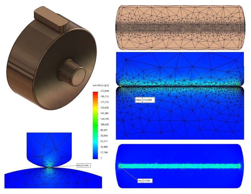
I'm designing a cam driven engine. I do all the calculations in Excel then export the results as equations to Solidworks where I create 3D models and run analysis to confirm my Excel calculations. The Excel calculations related to the most heavily stressed cam (R1 = 0.290", R2 = 2.468", 2,768 lbf force) indicate peak contact pressure of 248 kpsi over a contact length of 0.993" and width (2b) of 0.014" yielding Von Mises stress of 231 kpsi. The material is Maraging 350 steel having 319 kpsi yield, 0.32 Poisson Ratio, and 29,733 kpsi modulus of elasticity. I have confirmed my 2D calculations with several on-line calculators, so I'm confident they are correct. The 231 kpsi Von Mises result is, however, uncomfortably near the 319 kpsi yield.

When I run the same conditions in Solidworks FEA, I get a peak Von Mises stress of 213 kpsi. At first glance, that seems to correlate well with my 2D Excel result of 231 kpsi. Unfortunately, the Solidworks result reflects a hot element, and the rest of the surface shows a much lower Von Mises stress, typically below 138 kpsi. I extracted the stress and contact force data from the contact patch and confirmed it is a 3D Mohrs Circle calculation.
My question is simply this: Should I trust the Solidworks 3D results or my own 2D calculations when evaluating the design for margin?
