Eng-Tips is the largest engineering community on the Internet

Intelligent Work Forums for Engineering Professionals

swept boss option greyed out 1

Status
Not open for further replies.

jsutton88

Mechanical
Jul 9, 2015
4
0
0
US
I'm trying to do a swept boss and have created the path and profile.
gastray-fix_ccfqij.jpg
gastray-fix2_fbxj4q.jpg

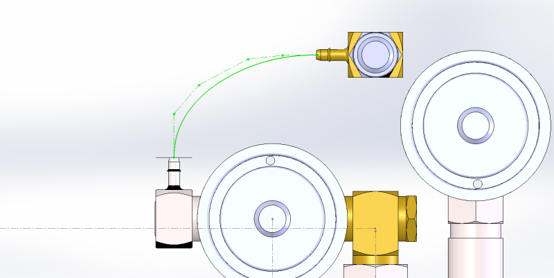
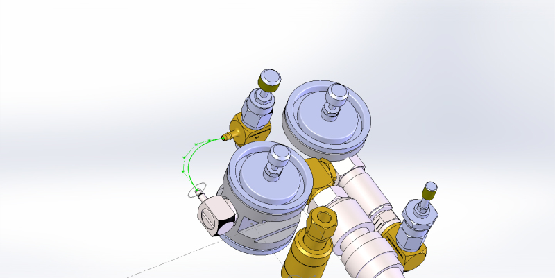
Here are a couple jpgs of the layout. I'm sure my path plane is perpendicular to the profile plane. However the option for swept boss is greyed out? Can someone help out on this?
 
Replies continue below

Recommended for you

When I do a sweep--and particularly with a spline-based path, I always sketch the profile on a plane that is created on the end of the spline path (pick the spline and end point to create your plane). That's the only way to truly know your profile is perpendicular to your path. Also, back in the old days of SW, you had to create your profile after you created your path. The practice I mentioned above makes certain that is always the case, whether still necessary these days or not.

Try that out and see if it works.


Jeff Mowry
A people governed by fear cannot value freedom.
 
jsutton88,

This is an assembly. You need to be editing a new part in the context of the assembly. There are only a few features you can add at an assembly level and most of them are cuts or welds.

- - -Updraft
 
I was thinking the same thing, Updraft, but I don't even have a sweep feature icon that shows up when I'm in an assembly, never mind being grayed out. Figured he might have been working in a multi-body environment.

Jeff Mirisola, CSWE
My Blog
 
I think your right Theophilus and I created a plane at the end of the path perpendicular to the path, still does not work. However although all sweeps are greyed out but if I type swept in the search box, the option for swept cut comes up. Then I use that and the preview shows the tubing exactly as I want it, but of course it's a cut and you can cut air, so it disappears. Also I don't know how to create this in anything but assembly, not sure if there is another option?
 
Where you have the sweep path, open a new part document and copy/paste the path, then sketch your profile. Create the sweep and insert the new part into your assembly. Or, create it in-context of the assembly. Your choice.

Jeff Mirisola, CSWE
My Blog
 
jsutton88,

From your comments it seems as though you might be pretty new to SolidWorks. For one you mention swept cut when you should be making a solid so it would be a swept boss, not a cut. Your other comment "Also I don't know how to create this in anything but assembly, not sure if there is another option?" indicates a lot as well. An assembly is an assembly of parts and not an environment to create new parts per se. You have a parts environment and then an assembly environment to put those parts together.

We are all too happy to assist you, but it appears you would dramatically shorten your learning curve if you were to go through the SolidWorks tutorials (go to Help -> SOLIDWORKS Tutorials).

- - -Updraft
 
Thanks JMirisola that will work. Updraft, I've had 10, years experience with ProEngineer and several years of Solidworks before I retired several years ago. True I'm a little rusty with solidworks getting back into it now and I do tutorials almost everyday. I know the difference between a cut and a boss, if you read my post correctly you would see that. I don't appreciate being criticized for asking for help!
 
I'm sorry you were offended. It was certainly not my intent. Your most recent post talks about swept cut and that was what I was responding to. I do see that your OP mentions swept boss. My post was not at all any kind of criticism, but instead was trying to be constructive. Again, my apologies for offending you, but if you were to review my posts here and elsewhere you would see that they are always trying to help people.

- - -Updraft
 
Updraft, the tutorials and the help items of Solidworks are designed to provide more of an idealistic than of a practical way of learning. Made an error in writing down a dimension? Too bad, there is no explanation in Help how to correct that and the Edit-Undo is also greyed out. Need to move one plane a bit further away from the base? Too bad, the selection of that plane is not done just by clicking on the selection menue and marking, and no explanation of how to do that via the non-intuitive and, for a learner: deeply hidden way is not available. Need to extrude with a 2 degree inclination of the planes because you make a mold? Maybe you find out that after you have mastered an initial two years of daily practice. Why isn't it possible to find an answer on these simple questions, so that that one thing in the drawing an be corrected instead of throwing everything away and having to start completely anew?

SW is absolutely great but for the person, who does not continuously dedicate his whole working day on learning and using it but needs it as a secondary tool the non-expert-unfriendly help makes it too complicated. And that is a big market that with little effort could be accessed. It is not the programme that is presents the complication, but the difficulty of the experts to understand the problems of the lesser-experienced person's, who does not want/need to work with all the bells and whistles.
 
You can create/edit parts in an assembly environment. It's how I build most of my tooling assemblies because it ensures that your mating components have matching lines, etc. In this case, you could make a new component within the assembly, and then edit it just as if you were in the new part dialogue, the only difference being you can reference sketches of the other components. This is also handy if something changes on a referenced sketch, it updates the new part automatically.

E. Morel
M.E.
 
I took a few minutes to run through this in the fashion I eluded to above.

1) I made a quick assembly consisting of two tubing connections, mated where I wanted them to be for this example (5 inches apart vertically and horizontally, but sharing a center plane). See Image ASSY1.

2) Select Insert >> Component >> New Part. Click in empty space on the screen. This adds a new part to your assembly tree. Right click the new part, click "Rename" and name it something you want, I named mine "TUBING". Right click again and "Save Part (in external file)" and select where to save the model. See image ASSY2.

3) Right click the new part and click "Edit Part" to being editing the new component. Your existing parts in the assembly will go transparent. I like to turn on any sketches from existing components in the assembly that I can use as reference lines. In this case, I turned the sketches on visible for both tubing connections. See image ASSY3.

4) Start a new sketch on whatever plane is your aligned center for both parts. In order to use the existing sketches as reference, I like to use the Convert Entities tool to make the sketches usable relations in the current sketch. In this case, I used the Convert Entities tool and selected the center lines of both tubing connections. This makes them usable lines in my new sketch. See image ASSY4.

5) Now, on the center plane I draw my sweep path that I want my tubing to take, mating it to the converted center lines from the other two parts. See image ASSY5.

6) Now I sketch the profile on the plane that I want, ensuring the center point of my profile is on the path line. See image ASSY6.

7) Now I simply use the Swept Boss tool to make the sweep. See image ASSY7.

8) Once complete, exit the part editing mode just like you would edit the sketch. See ASSY8.

The good thing about this, is that if I change the distances of the tubing connections and where they are mated, the tubing will automatically update and follow, since I mated the sketch to those two parts.

-E
M.E.
 
 http://files.engineering.com/getfile.aspx?folder=06d17d60-2175-453b-b29c-3eba06427e9d&file=TUBING_SWEEP.zip
Sorry I was a little grumpy last week especially after hearing the tutorial word. I agree with Laeddeal in that many tutorials do not address problems many of us face and having someone looking directly at the problem would be more useful. Not to mention the YouTube Solidworks videos posted by non English speaking people in English. These videos would be more effective if they were presented in the presenter’s native language. I work alone and have no one to ask Solidworks questions to except forums like this. I’ve worked in companies before where other Solidworks people worked there as well, such an advantage to have other people in your environment to talk about SW issues.
I was able to create this tubing in part mode after I laid it out in assembly. I was certain I was able to do this in assembly in the past but I was probably thinking ProEngineer. However after reading Emorel22’s post it looks like it can be done in SW as well. I will review Emorel’s post in detail as I know this will come up again.
Thanks for the help!
 
Status
Not open for further replies.
Back
Top