Continue to Site

Eng-Tips is the largest engineering community on the Internet

Intelligent Work Forums for Engineering Professionals

  • Congratulations SDETERS on being selected by the Eng-Tips community for having the most helpful posts in the forums last week. Way to Go!

Swept Tool related Question.... 2

Status
Not open for further replies.

SORJM

Computer
Apr 5, 2016
30
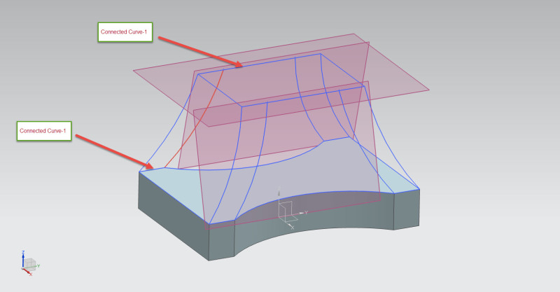
I want to join the following two connected curves by the help of 6 Guides displayed in the image to create a solid Body.
I am using NX 10. In swept tool I can use only 3 guides.
Please tell the suitable way to form such type of solid using more than 3 guides.
I am a new user of the software so post your reply in detail so I can understand easily.
Sweep_rwxyhy.jpg
 
Replies continue below

Recommended for you

Probably using the wrong tool. More than 1 way to do this, but this is the simplest, IMO.

NX9_Through_Curve_Mesh.prt

Tim Flater
NX Designer
NX 9.0.3.4 Win7 Pro x64 SP1
Intel Xeon 2.53 GHz 6GB RAM
NVIDIA Quadro 4000 2GB
 
Here's how I would do it to retain all edges - a bit more involved, but more precise with the edges, IMO.

NX9_Through_Curve_Mesh_Patch.prt

Tim Flater
NX Designer
NX 9.0.3.4 Win7 Pro x64 SP1
Intel Xeon 2.53 GHz 6GB RAM
NVIDIA Quadro 4000 2GB
 
I prefer this method - might be a little more robust if drastic changes are made to the base and/or top. Watch the Sew - for some reason it does matter what surface you use as the Tool (use the middle rounded surface based off the arc on the base).

NX9_Through_Curve_Mesh-o-rama.prt

Tim Flater
NX Designer
NX 9.0.3.4 Win7 Pro x64 SP1
Intel Xeon 2.53 GHz 6GB RAM
NVIDIA Quadro 4000 2GB
 
Thank you for the detailed reply the first solution did not worked. But other ways of creating the body worked.
It means there is no straightforward tool to create such body. Otherwise in Solidworks or Inventor it can be created easily with Loft Tool which saves a lot of time.


I would have used Surface Thru Curves using the 'Point' method to align the 'features' of the first profile to the 'features' of the second profile.

John R. Baker, P.E.
EX-Product 'Evangelist'
Irvine, CA
Siemens PLM:
UG/NX Museum:

The secret of life is not finding someone to live with
It's finding someone you can't live without
 
In Catia it can be done very easily using "Multi-sections Solid" command. Does NX offer something similar?
 
Surface through curves will not do since the intermediate shape should follow the 8 guides. ( Through Curves will be linear between the profiles since we have 2 profiles.)

"Multi sections Solids" IS what Tim is using. in NX.
In NX the corresponding feature is called Through Curve Mesh .( and Through Curves)

See similar case in
Note that the selects the first cross string again as #5 to close the body.
( I do not know why he uses Bridge curves in between, but thats a different question.)


Regards,
Tomas
 
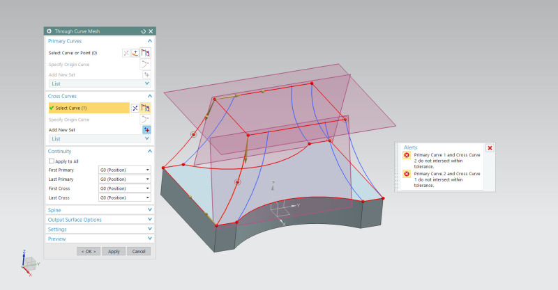
Through Curve Mesh is not working following error occurs when it is use.....
Sweep-2_aue7qc.jpg


I am attaching the file anyone can connect it with the suitable tool.
 
Yes, there is a straightforward way of doing it if you understand how to use the commands properly as well as have valid base geometry from which to create the sheets and/or solids. For lofting, Through Curves and Through Curve Mesh are the 2 commands that will give you the most control of a lofted body. Swept is the last command on my list because you are limited with the number of Guides AND you cannot control continuity. Read the NX Help docs if you're having issues figuring out how to properly use a command.

The error you're getting is stating that your curves and/or edges do not intersect within tolerance. That is usually not a command related issue, but rather an underlying geometry issue (curves). Check the distance between the curves used to create the base solid body and the vertical arc-looking curves. Fix those issues and the command will work just fine.

Also, I hope you're not picking ALL the curves as cross curves - cannot tell because you have both the Primary and Cross Curves List collapsed. Pick the base (Primary 1) and top "box" (Primary 2) as your 2 primaries, then however many of the 8 most vertical curves as your cross curves. Make sure the vector directions (yellow arrows) point in the same general direction (clockwise/counterclockwise for the closed curve loops). I'd be more than happy to work with your model, but I'm on NX9.

If you're only trying to create the left-most surface and not the entire body as a single solid, then don't pick the entire set of closed loop curves (you can, but it's completely unnecessary) - pick the 2 curves parallel to the X-axis as your 2 primaries & the 2 most vertical curves on the corners as your cross curves. Again, if they don't intersect within the intersection tolerance, then you're going to continue to get this same error message.

Tim Flater
NX Designer
NX 9.0.3.4 Win7 Pro x64 SP1
Intel Xeon 2.53 GHz 6GB RAM
NVIDIA Quadro 4000 2GB
 
Tim, are you working in Inches ?
The tolerances on this particular model is what produces the error messages. (I checked the distance between the bottom/ upper section to a couple of the "cross curve arcs", i get distance = 0)
If i open up the intersection tolerance, it immediately creates the sheet/solid.
In my session the intersection tolerance and distance tolerance is 0.0004 [in]

What should the intersection tolerance be default ?
( I think that it can be pretty large before it starts affect the resulting shape.)

Regards,
Tomas


Here's another solution, maybe a more "different" way of doing it. I used the 4 corner-arcs for a Through curve feature ( what other systems call "loft") and a degree 1 to get sharp corners.
then Through curve mesh in the "rounded area" only + trim body.
This method has the benefit of very light math due to the simple definition. ( can be seen on the filesize [MB]) + the features update fast.
( Instead of a single feature which has to interpolate the entire shape and therefore becomes heavy/complex i use 3 very simple shapes and Boolean these together.)

( If you have the Studio Surfacing license, the Studio Surface does a better job than the Through Curve Mesh since it has the option "Split output along boundary curves".)

Have a look.
Tomas
 
 http://files.engineering.com/getfile.aspx?folder=dd572b04-5e93-4306-978a-c74a68505b5d&file=Throughcurves--n-mesh.prt
Tomas,

I am working in millimeters. I could be wrong, but I believe out of the box NX is set to 0.02 or 0.025 regardless of units - has been a long time since I did an install myself. For inches, I'd be using something in the neighborhood of 0.001 for my Modeling Distance tolerance because it equates to roughly 0.025mm, which IMO is pretty acceptable for most automotive related models on which I've worked.

With the 2nd & 3rd examples above, I ran into distance errors when trying to Sew & found that ordering the sheets in a certain manner during the Sew procedure affected the outcome. NX didn't seem to like the top, bottom or the surface with the planar arcs on the floor (XY Plane) as the surface to which all others were sewn. I had to use one nearest the 4 lower corners as the Tool.

I'm not sure why geometry that obviously intersects requires a larger tolerance in order to create the surface. The intersection is exact, so there shouldn't be a need for a greater intersection tolerance. I am also perplexed why the Sew order mattered.

Tim Flater
NX Designer
NX 9.0.3.4 Win7 Pro x64 SP1
Intel Xeon 2.53 GHz 6GB RAM
NVIDIA Quadro 4000 2GB
 
Thanks a lot Toost for posting a good way to create the solid. I find it quite convenient.
I shall try it in other place too[glasses]....
 
Status
Not open for further replies.

Part and Inventory Search

Sponsor