Continue to Site

Eng-Tips is the largest engineering community on the Internet

Intelligent Work Forums for Engineering Professionals

  • Congratulations KootK on being selected by the Eng-Tips community for having the most helpful posts in the forums last week. Way to Go!

swivel ball/cone torque 1

Status
Not open for further replies.

kbero

Mechanical
Apr 7, 2015
4
trying to work out an adjustable swiveling foot.

Would like to clamp a ball between two cones (would be threaded together) as illustrated. Known would be the contact angles (and thus the radii of the contact rings), the compression force along the common axis of the cones, and the friction coefficients. It would seem that the torque necessary to rotate the ball coaxially to the foot and the torque necessary to swivel off-axis would be different from each other -- how would I best calculate the latter?

Thanks in advance.
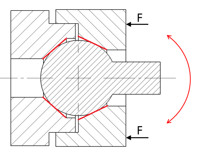
joint-2_qvl9bj.png
 
Replies continue below

Recommended for you

What makes you think they would be different?

-handleman, CSWP (The new, easy test)
 
kbero,

My first thought is that, given Newtonian friction, the contact radius is smaller for axial rotation.

I see no problem applying thousands of pounds clamping force by tightening your thread. It will be easy to exceed material yield stresses at the contact points, making your friction definitely non-Newtonian. Consider a spring loaded contact point.

--
JHG
 
Is the plan to loosen, position, then tighten to lock the pivoting/rotating shaft?
What does the through hole in the left housing do?

With 2 cones and the threads all fighting for location as defined by the sphere I picture some 3D jamming going on. Maybe that would be a good thing for your application. At some point I'd think about letting one cone float radially, or maybe replacing the cone in the left housing with a flat somewhat compliant surface.

 
thanks for the tips so far. There are several things I'm still thinking of doing regarding springs, floating, working with only one cone, etc.

@ Handleman -- When the ball is rotated coaxially to a cone, I was thinking that if you broadened the line of contact a bit (as would actually happen in reality), it would be rather like a cone clutch (integration of concentric rings).

But when the ball is swivelled along any other axis, I'm thinking now that it might be an integration of cross-sections that would look like increasingly smaller cylinders pressed into increasingly smaller V-blocks?
 
The friction force at each point is tangential to the surface of the ball and in a direction opposite to the motion.

The normal force at each point must pass through the sphere center. I think.

The integrals around the contact circles must somehow be a constant.

Simple thought experiment:

Consider a sphere resting inside a cone (point down, facing up)

If friction were directionally dependent there would be a clear preferred position. There is not.
 
I also think the torques will be similar, but the amount of leverage available will not be.

The shaft has a radius that is smaller than the ball and a length that has to be greater than the radius of the ball so the leverage is much different.

OTOH turning the ball means the line of action has a variable radius about the axis of rotation, while twisting the ball means a smaller maximum radius that is constant.

Example: Set a sphere at X0, Y0, Z0 with the lever initially along the Z axis and a circle of contact in the X-Y plane.

Twisting the lever about the Z axis places all the points of contact as contributors to resisting torque with the radius of the sphere.

If the lever is moved towards the Y axis, rotating the sphere about the X axis, then the contact along the X axis will contribute no resistance because there's no leverage against rotation, while a point on the sphere at the Y axis will resist with leverage of the radius.

So I'm inclined to think some integration is involved to determine the transition from being similar to being as different as they would be in my example.
 
Wouldn't there be a slight difference in breakaway friction when the stud is rotated about its axis in the direction the cone threads were tightened versus the opposing direction? Turning the stud in the same direction the cone threads were tightened would add to the clamped preload on the ball, while turning the stud in the opposite direction would relieve the clamped preload on the ball.
 
Assigning the center of the ball as "0" and assuming no flat spots at contact areas and a point of contact at the centers of each contact area for friction; if you were to rotate the lever about "0", ie, in the same plane as the drawing, you can visualize the frictional force perpendicular to the ball radius from which you can calculate the required torque; when rotating the lever perpendicular to the long axis of the handle, the frictional force will be perpendicular to the radius again but with a different direction and the torque needed for that rotation will require a radius value diminished by a sine of the angle formed between the diminished radius and the ball radius based on the drawing presented.
 
There likely may be a difference between theory and practice with this joint. Think about the minimum number of contact points required between the spherical ball and cone surfaces to fully constrain the joint in all three translational axes. One condition might be three contact points between the ball and one cone surface with the total angular spacing between the three points >180deg, and at least one contact point between the ball and the opposing cone surface. If there were any radial runout between the two opposing cone surfaces when the joint is assembled, this condition could easily occur. The spherical ball will naturally find its own kinematically stable position given the overall tolerance stack-up when the two halves of the housing are threaded together.
 
Status
Not open for further replies.

Part and Inventory Search

Sponsor