Continue to Site

Eng-Tips is the largest engineering community on the Internet

Intelligent Work Forums for Engineering Professionals

  • Congratulations KootK on being selected by the Eng-Tips community for having the most helpful posts in the forums last week. Way to Go!

Swivel Wheel Offset 2

Status
Not open for further replies.

Toranag9

Agricultural
May 20, 2024
4
Hello gentlemen,

I fairly new to the forum and I am not an engineer just trying to learn as much as I can and grow my skills in the drafting area.
I have been tasked with figuring out why we are having such a hard time making this crazy wheel turn with the machine.
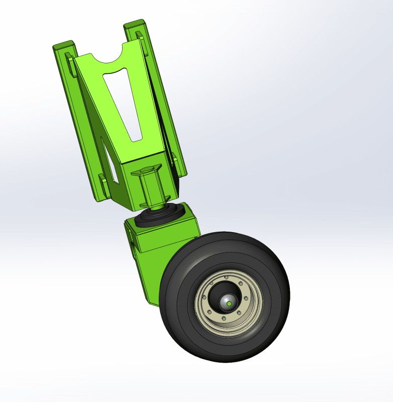
(I have attached a picture.) This is off a stockyard elevator where there are 2 wheels on one side that rotate with hydraulic cylinders and drive with some planetary wheel hubs.
The other side of the elevator has two crazy wheels like the one I attached, the machine weight is about 14000lbs according to SolidWorks. That is pretty accurate to what we physically have.
Now I was doing some research and I may be wrong but I found that increasing the wheel offset should be easier to rotate. Can you guys help me determine whether this is true and what I might be able to do to make this system work better. Also the Wheel is a 26x12 turf master form Eastbay tire. Please let me know if there are other things I may need to consider.

Thanks in advance!
 
 https://files.engineering.com/getfile.aspx?folder=0327d505-c6ce-4335-a51f-b1ab563c3c87&file=WHEEL_OFFSET.png
Replies continue below

Recommended for you

The "offset" appears to be caster, the distance from the contact patch to the place the turning axis intersects the ground. Think of the turning axis as the place force is placed on the lever that turns the tire, scrubbing the rubber on the ground. The greater the caster the longer the lever and so the easier to turn the tire. However, it also puts a higher load on the bracket that holds the turning axis for the same reason - increased leverage.

Keeping the tire inflated to the highest pressure it can handle safely will make the contact patch smaller and therefore allow the tire to turn more easily.

WHEEL_OFFSET_vfk6fc.png
 
Thanks for your response Dave.

So I am going to try and increase the distance and reinforce the bracket to account for the added leverage.
I will check to see that they are properly inflated.

Thanks.
 
I see so many machines with offset on caster wheels but with no noticeable camber that I have to wonder about the combination of caster and offset.
Note that the combination of offset and camber tends to raise the machine when the wheel is not in line with the axis of camber.
So when the machine is turning there are opposing forces.
The sideways movement of the machine relative to the contact patch tends to steer the wheel in the proper direction.
The camber action tends to oppose that action and return to wheel direction to alignment with the camber axis.
I suggest no or less camber.
I am assuming that this is a low speed machine.
Don't take my word for it.
Take a look at the caster arrangement on some zero turn lawn mowers.


--------------------
Ohm's law
Not just a good idea;
It's the LAW!
 
I could not tell if there is offset, but offset would make this so much worse.
 
Please excuses my ignorance with the terminology but there is no camber in this system, just the caster that gives it the "crazy wheel" effect.

The bracket sitting on top of the spindle; with the square tubing, basically has a bracket that allows us to hook up a hydraulic cylinder.
All 4 wheels have a hydraulic cylinder, and when its time to move the machine the cylinders extend to lift the machine off the ground and allow the wheels to rotate.
Its actually really similar to the zero turn lawn mowers, the difference is that the lawn mower has both drive wheels at the back of the machine and the casters at the front. We are looking for more of a sideways movement so we have both drive wheels on one side and the casters on the opposite side.
Now that I think of it I think it would be easier to change that, put the casters in front of the machine and the drives in the back.
I will look into that.

Thanks for the suggestions guys!
 
I mis-spoke. I used the word offset to describe the amount of caster.
The word may better describe a position to the side of a horizontal line drawn through the pivot.
Camber; In the drawing your support is not vertical.
Offset; Your wheel may not be in line horizontally with the pivot. Difficult to say from the drawing.
Caster; The amount that the wheel axle is displaced from the vertical center line of the pivot.
Try Zero camber and zero offset.

--------------------
Ohm's law
Not just a good idea;
It's the LAW!
 
Status
Not open for further replies.

Part and Inventory Search

Sponsor