Hello,
I hope you are doing well.
On one hand (Symmetry BCs in presured vessel) :
I have been strugling for a while, thinking about the proper way to define the symmetry conditions for the model I am studying.
It is a simple pressured vessel, then, as it is symmetrical, I am analyzing a quart of it. It has a load of 30 [bar] = 0.3 [MPa], which I apply through a NL analysis in 60 steps. The vessel is made in aluminum, with 6 [mm] thickness in the cylindrical part, which decreases up to 4.5 [mm] in the spherical part (I've applied a smooth transition).
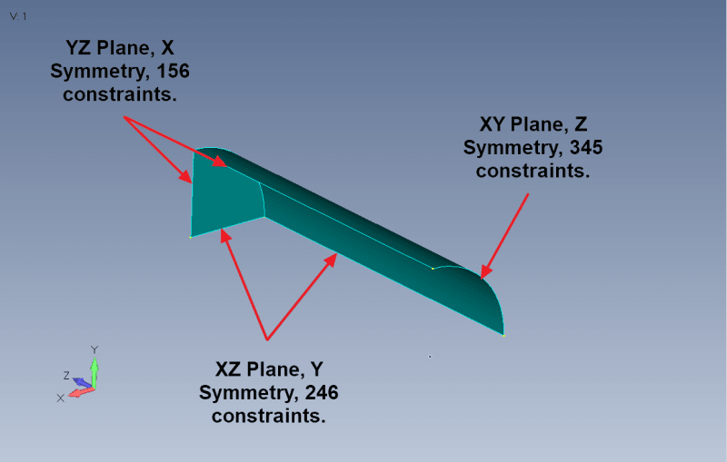
The problem is that I cannot figure out what are the correct symmetry conditions to apply.
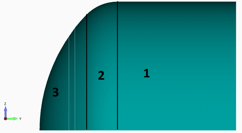
The model (image below) is made of the following sections :
1) Cylindric part
2) Toric part
3) Spherical part
For the cylindrical part, I have defined a cylindrical coordinate system and readily specified the symmetric BCs, but then I can't understand how to define the BCs. I have created a spherical coordinate system and assigned some BCs that I thought were appropriate after some thought.
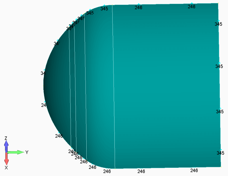
Clearly, the BCs I am applying are not correct since the results I am obtaining are not appropriate (figure below). The torical part is not expanding and I imagine it has something to do with the BCs.
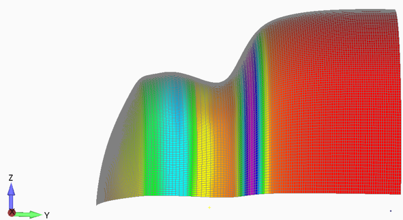
---------------------------------
On the other hand (NL material) :
I am defining a NL material, by introducing the stress-strain curve.
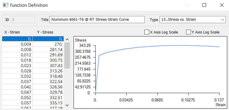
I would like to know which way is better for the nonlinearity type :
i. Nonlinear elastic : loading the curve into the the nonlinear properties part (in the material definition)
ii. Plastic : loading the curve in the same place but specifying the initial yield stress at 270 [MPa] following VM
In both cases, to test it, I take an element and obtain the stress-strain curve but I see that once the yield stress reached, the curve follows a straight line, i.e., strain increasing but stress stuck at 270 [MPa]. Any thoughts on what can be happening ?
Thanks in advance !!
Cordially,
EC
I hope you are doing well.
On one hand (Symmetry BCs in presured vessel) :
I have been strugling for a while, thinking about the proper way to define the symmetry conditions for the model I am studying.
It is a simple pressured vessel, then, as it is symmetrical, I am analyzing a quart of it. It has a load of 30 [bar] = 0.3 [MPa], which I apply through a NL analysis in 60 steps. The vessel is made in aluminum, with 6 [mm] thickness in the cylindrical part, which decreases up to 4.5 [mm] in the spherical part (I've applied a smooth transition).
The problem is that I cannot figure out what are the correct symmetry conditions to apply.
The model (image below) is made of the following sections :
1) Cylindric part
2) Toric part
3) Spherical part
For the cylindrical part, I have defined a cylindrical coordinate system and readily specified the symmetric BCs, but then I can't understand how to define the BCs. I have created a spherical coordinate system and assigned some BCs that I thought were appropriate after some thought.
Clearly, the BCs I am applying are not correct since the results I am obtaining are not appropriate (figure below). The torical part is not expanding and I imagine it has something to do with the BCs.
---------------------------------
On the other hand (NL material) :
I am defining a NL material, by introducing the stress-strain curve.
I would like to know which way is better for the nonlinearity type :
i. Nonlinear elastic : loading the curve into the the nonlinear properties part (in the material definition)
ii. Plastic : loading the curve in the same place but specifying the initial yield stress at 270 [MPa] following VM
In both cases, to test it, I take an element and obtain the stress-strain curve but I see that once the yield stress reached, the curve follows a straight line, i.e., strain increasing but stress stuck at 270 [MPa]. Any thoughts on what can be happening ?
Thanks in advance !!
Cordially,
EC