Continue to Site

Eng-Tips is the largest engineering community on the Internet

Intelligent Work Forums for Engineering Professionals

  • Congratulations KootK on being selected by the Eng-Tips community for having the most helpful posts in the forums last week. Way to Go!

System curve: Additional streams on pressure side

Status
Not open for further replies.

markboc

Bioengineer
Sep 1, 2020
19
Greetings!

Hopefully you can enlighten me on the following problem. Image a situation like depicted in the drawing. For the pump I'd like to calculate a system curve, so basically stream 1 and 3. I have trouble incorporating stream 2 into the equation for the following reasons:

- Stream 2 has a different density than Stream 1
- Stream 2 is a utility / mains line (think water), hence it is not feasible for me to get a clear of the piping / pump for stream 2
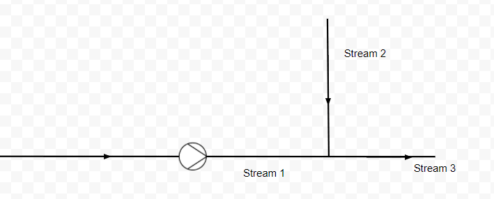
- however I know the desired volumen flow of Stream 2 and I can probably find out its pressure​
- and I also thought parallel pump calculations (known) are restricted to pumps with a shared suction side​

Unbenannt_kgeygl.png


1 ) How will the different density of the mixture (I kept the PID simple, after merging both streams there's a mixer) influence the system curve? I know that for a single medium the density does not matter as we are speaking of pressure in terms of equivalent heights.

2) The utility stream with its inherent pressure will also create a flow, how does that influence the system curve?

My ideas:

Premise: I used MS Excel to calculate the pressure losses across individual piping segments and thus create my system curve.

1) For the initial calculation of my system curve, I will add the flow of Stream 2 to each of my pressure loss calculations for Stream 1 after merging. E.g. if the pressure loss for a flowrate of Q1 was calculated as H = f(Q1) for Stream 1 it is now H = f(Q1+Q2) for Stream 3

2) At the t-junction the pressure should be equal for Stream 1 and Stream 2 to avoid reverse flow.

All flows are liquid, the densities vary by a factor of 2 at most. Stream 2 flowrate may vary between 1.5 to 20 times Stream 1 flowrate.

If anyone could give me pointers in the right direction or what assumptions may be valid I'd be very grateful.
 
Replies continue below

Recommended for you

1) You density shows up in the Reynold's number - rho*v*d/u. A lesser density will mean a lower Re and higher friction factor.

2) It will modify the pressure loss of Section 3.

Your premises:

1) Correct. Flow parameters in Section 3 (density, temperature, viscosity, etc) should reflect the flow and composition of the new stream.

2) Correct

The main unknown is the pressure source type and piping arrangement for Stream 2 and where Stream 3 ends. You can handle this a couple of different ways. First, do you know the endpoint pressure of stream 3? I.e. does it empty into a tank at a known pressure? If so, you can set up your system equation with a known end-point pressure and work backwards from there using the points you mentioned in your OP. In this arrangement, you would only need to pick a flow value for stream 2 to solve the equations.

With Stream 2 being up to 20x the flowrate of Stream 1, this seems like an injection pump that is pumping into a main header. I would imagine the pipe that contains streams 2 & 3 is quite large compared to Stream 1. If so, the marginal contribution of Stream 1 to backpressure in Stream 3 may not be very high. In this case, you can just model Stream 1 only with the assumption of a set value for pressure at the junction of Stream 1, 2, and 3 that is relatively unaffected by Stream 1 flow rate. You can then vary this pressure assumption (i.e. the main header pressure) to see how the system curve and pump performance changes as Stream 2 flow goes from 1.5x to 20x Stream 1 flow.

If the pipe sizes are relatively close and Stream 1 will provide a not-insignificant change in pressure loss along Stream 3 (compare the pressure loss of Stream 3 with Q1 + Q2 vs the pressure loss from Q2 by itself), then you will need to model the effect of backpressure on Stream 2, necessitating more information.

Overall, you need to find out/provide more information about Stream 2 and Stream 3. The above suggestions make some big assumptions that need to be verified - i.e. if Stream 2 is a variable speed pump and pipe sizes for Stream 2 and 3 are not much larger than Stream 1, you'll need to actually model Stream 2 and its pressure source as well.

 
The fact that you're basically injecting sometimes small quantities into another line will complicate life a LOT.

Not sure what you're really trying to do here, but you may be better with a PD pump where you only need to know max pressure at your junction point and forget about a system curve.

Remember - More details = better answers
Also: If you get a response it's polite to respond to it.
 
To make a total system curve you must know the head vs flow curve of stream 2 as you must be able to inject at a minimum of that same pressure, which is also the minimum control pressure for stream 3, to which you will add the additional pressure needed to get your stream 1 flow moving into and down that 3rd line stream.

If you don't know that information, you will have to design your pump to inject your full stream 1 flow into that system at an /some kind of/ estimated maximum head. NOT a very ideal solution.

You might want to consider placing check valves on streams 1 and 2 before the junction or you might sometimes wonder where the combined flows are really going.

 
Agree with LI, if the fluid volume is so important, why don't you use PD pumps and forget about the system curve?
 
Thank you all very much for your great replies! Really appreciated!

I'm trying to adress all of your input.

TiCl4 said:
1) Correct. Flow parameters in Section 3 (density, temperature, viscosity, etc) should reflect the flow and composition of the new stream.
Great! So I just adjust these parameters in my calculations. Do I still need to factor in the added volume flow like I suggested?

TiCl4 said:
The main unknown is the pressure source type and piping arrangement for Stream 2 and where Stream 3 ends. You can handle this a couple of different ways. First, do you know the endpoint pressure of stream 3? I.e. does it empty into a tank at a known pressure? If so, you can set up your system equation with a known end-point pressure and work backwards from there using the points you mentioned in your OP. In this arrangement, you would only need to pick a flow value for stream 2 to solve the equations.
Stream 3 and the end point, in this case indeed a container with atmospheric pressure, is known. I don't really know what you mean by working my way backwards. Right now I calculate the pressure loss along each pipe (segment) for different flow rates. From that I can plot my system curve. After fitting it with an equation I calculate my operating point. I also know the desired flow value for stream 2. For stream it would be something like:

H = Δh + h[sub]friction loss[/sub] + p[sub]static[/sub]
where h[sub]friction loss[/sub] is a function of the Reynolds-number, pipe roughness, all pipe fixtures (90° bends, valves, ...)

H(Q) for different flow rates yields my system curve. Let's say there is no stream 2, but stream 3 is of a different size. I would do the same for stream 3 and get:

H1(Q) and H3(Q) for different rates. Since the pipes are in series I simply add H for equal Q, so my system curve is:

Hsys = H1 + H3

Let's say for example for a flow rate of 1 m^3 / h we get H1 = 3 m and H2 = 4 m, a point of my system curve would be H(1 m^3 / h) = 7 m

Now stream 2 is taken into account, if the pump still delivers 1 m^3 / h, the pressure drop H3 will be different because there is a different friction loss due to the additional flow of stream 2, probably more than 7 m. I'm not a native speaker, so I hope I'm asking in an understandable way: How can I account for the varied flow rate? With the endpoint pressure known etc. I still struggle with the diffrerent flow rate. Accounting for the change in density has been solved by you.

I suspect the issue itself is resolved anyway (see below) but I am still interested on how I would do this in general.

-sixty five said:
To make a total system curve you must know the head vs flow curve of stream 2 as you must be able to inject at a minimum of that same pressure, which is also the minimum control pressure for stream 3, to which you will add the additional pressure needed to get your stream 1 flow moving into and down that 3rd line stream.
Stream 2 is water mains, I will have to investigate further how stream 2 is fed from there exactly. Currently I assume the water which is supplied at a relative high pressure, is fed into stream 2 through a valve which controls the flow rate by inducing a large enough pressure drop. I could probably calculate the necessary pressure drop across the valve for certain flow rates and get my head vs flow curve from there.

-sixty five said:
You might want to consider placing check valves on streams 1 and 2 before the junction or you might sometimes wonder where the combined flows are really going.
My diagram is nothing more than a sketch of the situation. Check valves are in place in stream 1 and 2 before the t-junction, but thanks for pointing it out!
@LittleInch @bimr
Sometimes life can be so easy... The pump in question indeed is a gear pump and I just realized why that's important. It will deliver a certain flow rate depending on it's rpm, almost independently of the pressure loss because of its steep characteristic curve. How I missed that earlier is beyond me.


I logged in today to tell you that your system curve could be developed from stream three alone, if you had that data, but I now see that TiCl4 has already mentioned that alternative.

In any case, your gear pump has already solved your problem. Happy days.

 
Markboc,

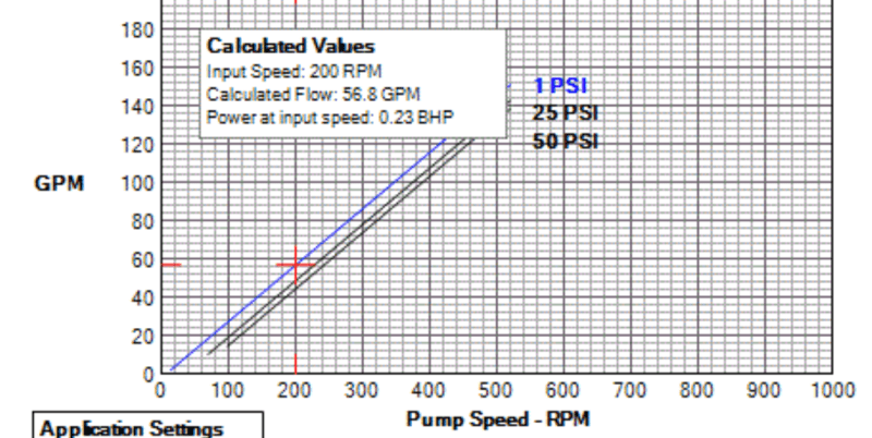
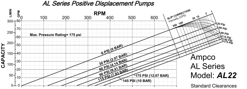
Just something to check on the gear pump if you are pumping low viscosity liquids (less than 100 cP): Look at the manufacturer's pump curve. It should have a slip correction factor (similar to the one below) on it based on differential pressure across the pump and liquid viscosity. Manfacturers (like Viking) may also provide a calculator instead of a published pump curve. If you are taking a large differential pressure across the pump and you are pumping water-thin liquids, your pump capacity will likely be reduced by a significant amount.

Examples:
Gear Pump curves from Viking calculator. Top curve is 1 psid and bottom curve is 90 psid.
image_ccrgn1.png

image_pvake8.png


Lobe Pump Curve with built-in viscsoity/pressure slip correction.
image_ssvich.png
 
Thank you for bringing up this additional consideration! The curves supplied by the manufacturer are specifically for the viscosity we supplied, but I will check back with them if the slip is really considered in that diagram.
 
Status
Not open for further replies.

Part and Inventory Search

Sponsor