AtomicSheep
Structural
Hi,
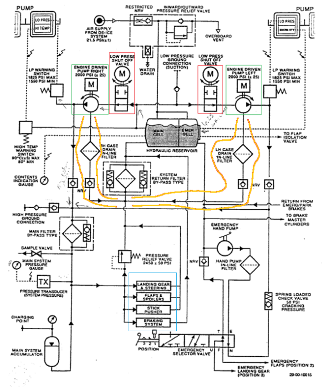
I've got a couple of questions about this system. The way I see it, this system has two sections, a high pressure and a low pressure section. Before the engine driven pumps in green, the system is low pressure and high pressure thereafter.
I guess this is why the shut off valves in red are called low pressure (because they are located int eh low pressure section and not due to their nature of operation) but correct me if I'm obviously wrong.
Before I go into the questions I just want to point out that the whole point of this system is to drive the components in the blue box.
The first question that I have is... what happens to the components in the blue box if you switch switch the LP Shut off Valves in red to off? The way I see it, this hydraulic system is like power steering, so with the LP valves turned to off, you effectively lose power steering? So effectively, controlling those components becomes very difficult?
The second question that I have is a bit basic, but I'm finding it hard to grasp how you can have a high pressure state after the engine driven pumps and a low pressure state before the engine driven pumps. Do the pumps create a suction which then starts a circulation of fluid through the system first from the pumps then through the components in the blue box, then this fluid is pushed at high pressure back into the main cell and then the process repeats?

