Continue to Site

Eng-Tips is the largest engineering community on the Internet

Intelligent Work Forums for Engineering Professionals

  • Congratulations KootK on being selected by the Eng-Tips community for having the most helpful posts in the forums last week. Way to Go!

T-fitting after pump - Calculating flowrates 1

Status
Not open for further replies.

Carl-E

Mechanical
Dec 18, 2023
6
Hi!

We are planning a process system. There will be a t-fitting after a water pump with a known flowrate.

After this, there will be a t-piece going to two different chambers with slightly different air pressure.

I have calculated the difference in flowrate on both ends after the t-piece using the following method:
The bernoulli equation is set up, with height=0 and removed from both sides. Pressure is different on both sides of the t-fitting, and this is known. Both velocities are unknown. I solve the equation and get something like 1,75=v1 + v2. Then i use Qtotal=Q1+Q2, and get another way of expressing v1 and v2. I then get two equations with two unknowns, and I can solve it. Ending up with a v1 is 20% greater than v2, which makes sense.

Anyone think this is wrong? I am unsure if it is actually correct to use bernoulli in this way....

Regards Carl from Norway
 
Replies continue below

Recommended for you

At the middle of the T there is only one pressure. How will the pressure be different?
 
If you're trying to figure out the flow rate to either system on the outlet of the tee, you need to be modeling/reviewing the entire system. While you may be able to ballpark it if the outlet piping is identical, if it's not you should consider all elbows/pressure drop sources in the calculation.

Not sure if you're trying to balance the downstream air pressures to get equivalent flows or what...
 
Carl said:
We are planning a process system. There will be a t-fitting after a water pump with a known flowrate.

After this, there will be a t-piece going to two different chambers with slightly different air pressure.

So, water or air?

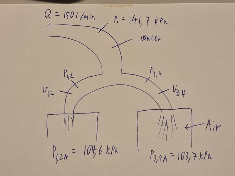
The solution starts with a sketch of the system. Since you need to draw one for yourself anyways, why not share it with us.
 
20231219_075824_krbeef.jpg


I have some sensitive IPR in my sketch, but I created another. What I am really wondering about is: During constant flow, will P1,2 and P3,4 be different?

I have taken the pump pressure 141,7 kPa and added the pressure above atmospheric from each chamber to P1,2 and P3,4.
P1,2= 144,6 kPa and P3,4= 143,72 kPa.
Put this into bernoulli, and got two unknowns in an equation (v1,2 and v3,4), and used Qtot=Q1,2 + Q3,4, and got another equation.
Solved this equation set, and got that v1,2= 1,95m/s and v3,4= 2,35m/s which may seem like a large difference due to the low pressure difference, but from our earlier experiments, it makes sense.
We are still slightly unsure if we have used the bernoulli equation correct here.
 
I've never though Bernoulli is relevant to these sorts of questions.

At the junction point, i.e. lower than P1, the pressure is the same.

If the distances are as you sketch and the orientation, then any slight difference will have an impact.

So a small length difference or in this case orientation can make the difference. Try having both pressures the same if possible and then see if there is a difference in flow.
try moving the incoming pipe around to avoid swirl having an impact.

Exit losses will have an impact.

So yes V3,4 as shown will be higher as you have a marginally higher pressure drop available and ~10% sounds about right, but better than that will be very difficult to calculate and in practice will be different. So much will depend on actual water velocity and how the flow splits at that tee.

How important is it to know to what level of accuracy?

Remember - More details = better answers
Also: If you get a response it's polite to respond to it.
 
Carl said:
During constant flow, will P1,2 and P3,4 be different?

You're pumping against a different head effectively, so sure, the flow will be different.

If it's really that important to the process, wouldn't you want to include some type of flow control valve in each line so that you can tune or control the flow as needed?

If you turn the switch on a the flows aren't right - because of all the other little things that will affect it - you can't show the flow your calculation and tell it "you need to be this because I calculated it on a napkin with the help of the internet!"

If you need the flows to be right, you need to add a valve to make them right.
 
I could clarify a few things. The t-pipe and resulting pipes are symmetrical.

3DDave (Aerospace)18 Dec 23 22:58
At the middle of the T there is only one pressure. How will the pressure be different?

- It makes sense that the pressure inside the t-piece will be equal, but how can I calculate the flow in each tube when the external pressure is different? The flow will be higher in one tube. If not Bernoulli should be used, what equation can I use?

We need to optimize on cost, so if we can drop valves and accept a slight deviation in flow, that would be best. To calculate the accept criteria, it would be best to complete the flow calculation and see its impact.
 
Is the flowrate for the pump truly known, i.e., a displacement pump?
 
There is a flowmeter after the pump. From the pump curve, we can see the pressure P1 also
 
You use pressure drop calculations, complete with entry / exit losses.

I'm not sure if the 141.7 kPa is at the centre point of the tee or somewhere else?

If it is then the difference between the two is 37 to 38, which isn't a lot.

However if the 141.7 is actually some distance from the tee then the first thing you need to do is figure out the pressure at the middle of the tee.

If this is much closer to the end pressure then the percent difference might become more relevant.

Remember - More details = better answers
Also: If you get a response it's polite to respond to it.
 
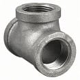
Is this a threaded tee that has H2O flowing in it?

tee_r3jbac.jpg


There are a few disturbances that need to be accounted for to make a good flow estimate.

Why use a flowmeter to solve for total flowrate and then calculate a result for the divided flow? Can you install another flowmeter and/or reuse the original flowmeter on one of the legs?
 
It is a glued George Fisher tee that has H20 flowing through it.

Building tests are expensive in our system, so a calculation we can trust can save us some money.

I think now that I have used bernoulli the wrong way.

Bernoulli should be used in the following method i think: P1......(the rest of the formula) = P1,2 ... + P3,4 ...
I can place delta P and delta v and solve for this.
 
Carl-E said:
Bernoulli should be used in the following method i think: P1......(the rest of the formula) = P1,2 ... + P3,4 ...

Bernoulli is only applicable along a single streamline. You can compare two separate streamlines (P1... = P1,2... and P1...= P3,4...) but you can't just add the total energies together, as the head losses will be different in each leg. If you do this out and include head losses it should boil down to a typical pressure drop calculation approach anyways, as others have suggested.
 
I actually disagree with the basis of why you cannot use the bernoulli equation in this way. After talking with one of our senior engineers. He told me my calculation is correct ecept from I have neglected friction losses, and viscous forces. Even though it gives a good estimate, and that is the objective of the calculation.

Bernoulli's principle can be derived from the principle of conservation of energy. This states that, in a steady flow, the sum of all forms of energy in a fluid is the same at all points that are free of viscous forces. This requires that the sum of kinetic energy, potential energy and internal energy remains constant.

Threfeore; From a tee, the big inlet, the energy going into the tee is equal to the energy going out from the tee. And furthermore, assuming the tee is symmetrical, and assuming laminar flow, the energy going out from each side of the tee will be equal. Hence, the bernoulli equation can be used like I suggested.

What do you think about this explanation?
 
Laminar flow? Calculate your Reynold's number.
 
"Except I have neglected friction losses and viscous forces (??)"

Error, that's quite a big neglect.

That's why bernoulli doesn't work in real situations.

Remember - More details = better answers
Also: If you get a response it's polite to respond to it.
 
Status
Not open for further replies.

Part and Inventory Search

Sponsor