Continue to Site

Eng-Tips is the largest engineering community on the Internet

Intelligent Work Forums for Engineering Professionals

  • Congratulations IDS on being selected by the Eng-Tips community for having the most helpful posts in the forums last week. Way to Go!

taking out eccentricity from precast wall to capping beam

Status
Not open for further replies.

4dmodeller

Structural
Oct 8, 2015
39
Hi all,
can someone remind me how to draw and calculate the correct strut and tie model/ (force through the reinforcement bar) to show how the ground floor slab helps take out the eccentricity from precast wall landing eccentric from the supporting capping beam?

i know it works but i just cant seem to recall how to draw one properly.

alternatively, ive justify that if the moment induced in the capping beam is this much, i will create a push and pull free body diagram in the ground floor slab to calculate how much reinforcement i need.

Thanks all!
 
 http://files.engineering.com/getfile.aspx?folder=c2d97793-9ecb-4508-a80c-6543f9fc7ffa&file=img-Z17103910-0001.pdf
Replies continue below

Recommended for you

If you're not relying on any fixity from the wall over, then the eccentricity will be taken out from developed rebar from ground slab to pile cap. I think the push pull analogy is the way to go. A Z bar with the vertical next to the precast wall would probably do the trick.
 
hi, would you be able to draw me the free body diagram around the 'z' bar?

thanks
 
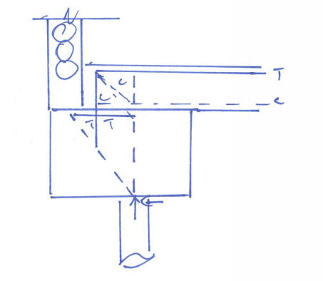
is it like this?
wall_to_capping_beam_kje4vv.png
 
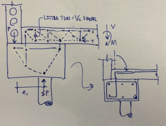
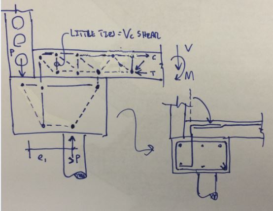
I've pitched a couple of options below following your lead for the desired load path. I think that the first one is the better option as it would require less of the Z-bars than the second and it represents a more direct path for the transfer of compression.

I'd like to think that BowlingDanish and I are on the same page here regarding the z-bars but, at the same time, I don't want to risk putting words in his mouth.

Capture_02_hk7rly.jpg


Capture_01_eky9el.jpg


I like to debate structural engineering theory -- a lot. If I challenge you on something, know that I'm doing so because I respect your opinion enough to either change it or adopt it.
 
Hi KootK,

sorry for the late reply. Thank you for the detailed sketch. That STM made a lot of sense. I was trying to draw one up myself but did not achieve a result as clear as yours.

Just to clarify that the C compression and T tension is supposed to be the other way around in your sketch..top of slab is in tension after all.

Couldn't the strut that changed from sketch 1 and 2 run straight to the pile? wouldn't that be more direct pathway?

Also, i would expect a high shear area just before the slab sits on the capping beam. Should there be another tie in this area?

Thanks.
 
4D said:
Just to clarify that the C compression and T tension is supposed to be the other way around in your sketch..top of slab is in tension after all.

Quite right.

4D said:
Couldn't the strut that changed from sketch 1 and 2 run straight to the pile? wouldn't that be more direct pathway?

I don't see how it could do that and also provide anchorage for the tie holding the left end of the slab down. Perhaps there are other STM's possible that could be set up to facilitate that. I was gunning for a reinforcement layout that would be as simple as possible.

4D said:
Also, i would expect a high shear area just before the slab sits on the capping beam. Should there be another tie in this area?

You'll need to assess shear along the length of the slab and provide shear capacity as required. That may or may not require reinforcement (hopefully not). I'd expect the highest slab shear to occur over top of the capping beam.


I like to debate structural engineering theory -- a lot. If I challenge you on something, know that I'm doing so because I respect your opinion enough to either change it or adopt it.
 
Actually, I see what you mean. The rightmost slab strut I my sketches should be flipped and tied.

I like to debate structural engineering theory -- a lot. If I challenge you on something, know that I'm doing so because I respect your opinion enough to either change it or adopt it.
 
Note that if you put structural loads into the slab on grade then you should design the SOG as structural concrete (ACI 318 for the States) and not a minimally reinforced SOG.
 
Is this a slab on grade? If so, what is the reason for tying it to the structure? We typically try to make a slab on grade a floating slab to minimize any interaction with the foundation, that may result in slab cracking.
 
Ughh.. I even botched my second model which I don't even like. There should be another strut coming up from the pile and hitting the rebar intersection above and to the left.

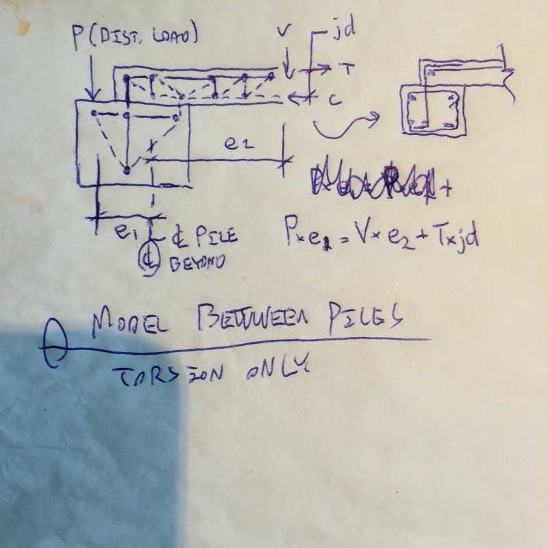
It would be great if you could post a plan view sketch. We've been exploring models that imply that all of your eccentricity is resolved by the slab at the pile. My suspicion is that the capping beams span between discretely located piles and that the eccentricity is mostly transferred to the slab continuously between piles.

I like to debate structural engineering theory -- a lot. If I challenge you on something, know that I'm doing so because I respect your opinion enough to either change it or adopt it.
 
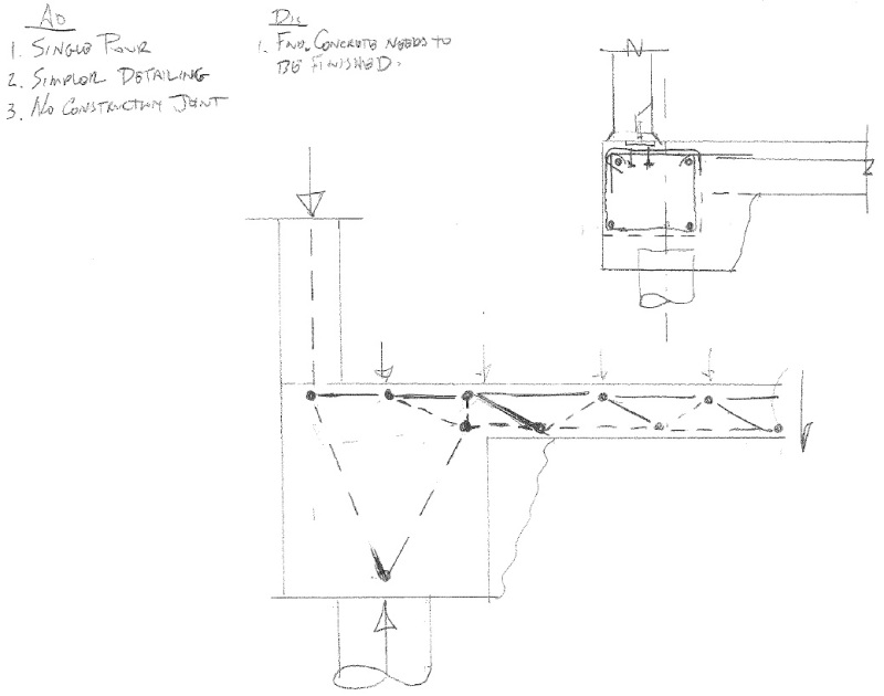
Here's the model that I'd use for the continuous model that I mentioned in my last post. At the piles, there would theoretically be no load eccentricity. Note, however, that STM provides a safe design, not necessarily a serviceable one. If the pile connection stiffness draws all of the torque, some cracking would need too occur to mobilize the STM mechanism.

image_zn8pi5.jpg


I like to debate structural engineering theory -- a lot. If I challenge you on something, know that I'm doing so because I respect your opinion enough to either change it or adopt it.
 
Just to beat this dead horse - It might make sense to put the slab and cap into the same pour.

PCGBSOG_ca5ooy.jpg
 
Status
Not open for further replies.

Part and Inventory Search

Sponsor