Continue to Site

Eng-Tips is the largest engineering community on the Internet

Intelligent Work Forums for Engineering Professionals

  • Congratulations waross on being selected by the Eng-Tips community for having the most helpful posts in the forums last week. Way to Go!

Tall Stud Wall / Window Wall Augmentation 4

Status
Not open for further replies.

Simba13

Structural
May 19, 2020
105
Morning all,

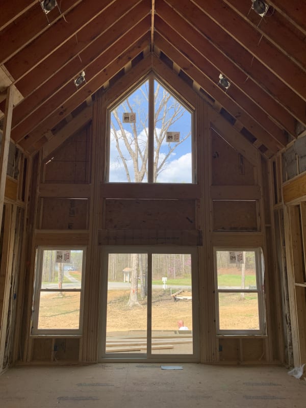
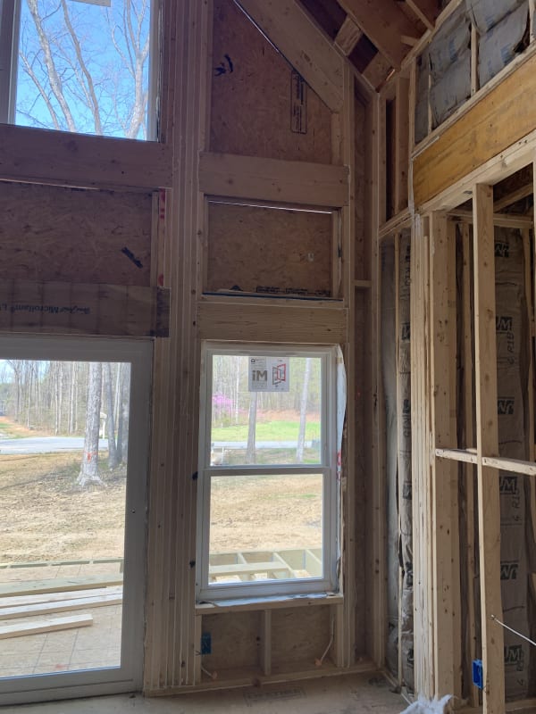
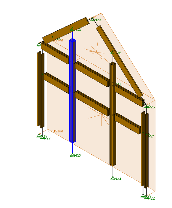
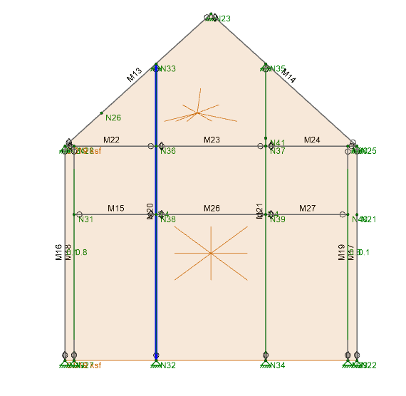
I'm looking for a bit of input on a tall wall analysis. We've got a Client that has come asking for help after building a wall beyond the limits of the code AND taller than the plans reflected. They raised the wall 2' and basically crossed their fingers hoping that the inspector wouldn't notice, no dice. So they're looking to us to hopefully find a way to solve the problem. I've modeled it in RISA 3d and I'm getting a midspan deflection of around 1.3", the wall is a gable/cathedral ceiling type and the peak is 19' high, 16' wide at the base. I'm only considering wind load at this point (i'll add in snow eventually). The wall is 2x6 with 4- 2x6 on each side of the largest window and then a couple 2-6's near the edge on both sides.

So, seeing as deflection is too high, but strength is ok (at least for just wind), how would you go about trying to modify this wall to bring down deflection? My boss had an idea about nailing a 2x8 flatwise (full length) to the back of the 4-2x6's to increase the moment of inertia and thus decrease deflection. I was just curious about how other engineers might approach this problem.

Thanks!

IMG_3139_2313_bwc96k.jpg


IMG_3140_2314_xsge8d.jpg


Realistic_Model_zvghr0.png


Wire_Frame_Model_obnulz.png
 
Replies continue below

Recommended for you

What wind load are you applying to calculate deflection? Remember that the building code allows you to use 0.42*W for your wind load deflection calculations. This is approximately equal to the wind load resulting from a 10 year MRI 3-second gust.
 
phamENG Oh man! You're right, I literally learned that from this very forum a while ago (possibly from you to be honest) and I totally forgot. The 10 yr MRI is 76 mph (Louisa County). q=.00256(Kd)(Kz)(Kzt)V^2 = .00256(.85)(.85)(1)(76)^2 = 10.68 psf I only show my math because that load seems a little small (though I guess that's sorta the point). This is already a serviceability load so I don't convert to ASD right? Just leave as is? (Using category C for Kz btw)

Seriously thanks, this is going to help deflection a lot, wind loads are almost half.
 
I'd agree with your boss. Only way to decrease deflection is to increase inertia for a given load. 2x6 might work. I'd investigate some 3/4" plywood glued and screwed across the assembly as a first option though.

Make sure whatever you increase the thickness by the client understands that the finishes may have to change. For example, sill depths, jam depths, etc all might have to be larger by the amount you fur out. If you don't tell them they might buy the same stock as everywhere else and go "FFFFFF*****CK" when it comes install time (and naturally blame you), and it's just better to cut that off at the pass.
 
Oh, as a follow up, I've seen some different posts on here about the deflection limits for walls supporting glass. What do you all usually go with for this sort of wall, l/240?
 
Enable Yeah, I was worried about the sill depth, it's already a built 2x6 wall so it's not as though you can change the sill without rebuilding the whole wall. With the decrease in wind loads as per phamENG the deflections are more reasonable, right around l/240. My boss is pretty sensitive to deflections in walls with a lot of glass (the windows shown aren't even all of them, more are to come, the wall is basically 90% glass) so plywood might be the best option at this point, we wouldn't widen the whole wall I guess, just deepen the trim in those limited areas.

Thanks [2thumbsup]
 
Simba13 said:
This is already a serviceability load so I don't convert to ASD right?

Correct. If you look at ASD load combination 6a, 0.75*0.6W = .45W, which is very close to the .42 conversion to 10 year MRI.

Yes, L/240 would be appropriate. If you don't need L/240 for finishes, you can reduce it to L/175 if you bump your wind load back up to 0.6W. (It's all there in footnote F.) I've heard the argument before that the L/175 and 0.6W only applies to the window frame (from the manufacturer), but I haven't seen any hard evidence of that so I try to avoid that interpretation. If anyone has the IBC commentary and can comment on it that would be nice.

Enable - there's no requirement in the code to design for deflection caused by the strength level wind or even a 50 year MRI wind load (which is approximately what the ASD level, 0.6W is) unless you're looking specifically at glazing supports. The IBC (and, more specifically in this case, the Virginia Construction Code) permit 0.42W to be used in deflection calculations. If you can make it work with the full wind load during design without adding much cost, that's great - but it's nice to have this to fall back on in situations where the alternative is to rip it down and start over. Always a good idea, though, to make sure the owner knows they are getting the absolute code minimum performance which usually isn't good enough for folks who can afford to put a room like that in their house.

 
Why on earth would you spend the time to model this in RISA? You should be able to check the deflection and strength with a calculator in under 2 minutes.
 
@phamENG, You mention LC6a, wouldn't that LC converted to a 10 year return result in 0.75(0.6)(0.7)W which is 0.315W. The 0.42 was derived for converting ultimate (LRFD) state wind to ASD 10 year returns based on 0.7 factor for 10 year design and 0.6 factor to convert from LRFD to ASD, hence 0.42W. The older IBC codes (when wind was still ASD level) used 0.7 factor in lieu of the 0.42 factor now days for wind deflection. The 0.75 factor in LC6a is to adjust because of the combination with other loading, ie. L and Lr, etc.., not to convert to 10 year return period, therefore you would apply the 0.7 factor in addition to the 0.75 and 0.6 factors in that specific load case.

Note that this factor only applies to Components and Cladding forces, and should not be used when using MWFRS loading.
 
Aesur - I brought it up only to point out that at least one ASD combination was already adjusted down close to that. I see where it probably caused more confusion than help. Thanks for straightening me out.


phamENG - no worries, honestly I was trying to makes sure I wasn't going crazy there with adding the 0.7 to ASD when using C&C.
 
I'm curious what is supporting the structural ridge (if it has one) in this picture? If it does not have one, what is keeping the roof from spreading?
 
XR250 funny you mention that. Two comments from the county (at least that the Client has asked us to deal with), one on the height of the wall and the second is for "collar ties need to be addressed on main gable at tall wall". On that point, can someone comment on their understanding of rafter ties vs collar ties?

My understanding is that collar ties are meant to keep the roof from spreading at the ridge due to uplift and rafter ties take out the thrust. Which makes sense since rafter ties are in the bottom third and based on a quick FBD any horizontal member above the mean roof height isn't going to have a moment arm to resist the horizontal (thrust) load (might be totally wrong here but that's what I'm seeing). So why does everyone I talk to insist on calling them collar ties? It seems like more than a semantic issue. This roof definitely needs rafter ties but whether or not it needs collar ties is debatable.
 
I do not disagree with everyone here on the need for a deflection check on a tall wall full of windows or the design recommendations given above...

However.. From a strictly (IRC) code perspective, I am not sure one is required (still not condoning it though). I ran into a similar circumstance recently with a clear-story wall. Did some digging in the IRC and came away baffled that there seem to be very little requirements for full-height studs at window jambs (king studs) for tall walls.

Unless I am missing something, here are the code references (IRC 2018).
IRC R602.3.1 Exception 2 allows tall walls up to 20' for non-loadbearing walls for 2x6 @ 12" o.c. (similar to the tall wall table in previous code editions)

IRC R602.7.5 and Table R602.7.5 require full-height studs at headers, but does not appear even close to being sufficient for tall walls. (only 1 king stud for up to 8' openings)

Unless I am missing a code requirement, technically your wall would be allowable per IRC with 2x6 studs and a single king stud at each opening. Crazy I know.
2015 had more rigorous king stud requirements but it seems to have been scaled back. It seems to me king studs for tall walls should be addressed separately somewhere.
 
Definitely needs collar ties? I don’t see how they can be added with that full-height window at the end.

More like “definitely need to find a way to resolve the roof thrust without collar or rafter ties”.

Might want to look at the load path for the horizontal reaction of those tall jambs as well. I’d worry more about load path than deflection.
 
Status
Not open for further replies.

Part and Inventory Search

Sponsor