Continue to Site

Eng-Tips is the largest engineering community on the Internet

Intelligent Work Forums for Engineering Professionals

  • Congratulations KootK on being selected by the Eng-Tips community for having the most helpful posts in the forums last week. Way to Go!

Tank Fluid Heating with Recirculation and Heat Exchanger. 1

Status
Not open for further replies.

Pavan Kumar

Chemical
Aug 27, 2019
338
Hi All,

I am working on a Anaerobic Digestion Project. The process involves heating the contents of the Hydrolysis and Digester tanks to 37 Deg C using a external Heat exchanger( with Glycol on the shell side) with a re-circlation pump. To develop a calculation spreadsheet I want to start with simple case assuming the tank contents to be just water. I want to calculate the heat input to this Heat exchanger to heat the tank contents from 10 Deg C to 37 Deg C. Pasted below is quick sketch. I want to know how to proceed with this calculation. I know the water temperature is not constant but would like get a methodology to start the calculations. Once I understand the methodology I will use the actual fluid properties. Any guidance would be very helpful.
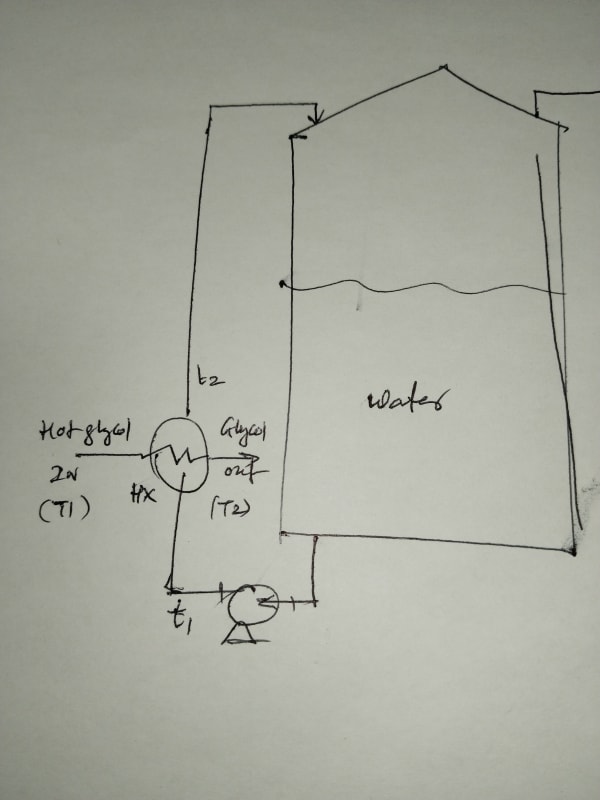
IMG_20240322_151308_xbav5m.jpg


Thanks and Regards,

Pavan Kumar
 
Replies continue below

Recommended for you

Hi LittleInch,

LittleInch said:
You might want to consider a pipe in pipe or jacketed pipe system or even an agitated tank with external jacketed pipes.

Current design with any sort of slurry or bits looks problematic.

Heat design it makes no real difference. Time to heat up is still your critical issue which you haven't let on so far....
Remember - More details = better answers

One of the existing Biogas Plant for the run by the same client is using Pipe-in-Pipe ( Double Pipe HX) as an external heat exchanger. Apparently they have pressure washing to clean the solids deposition from time to time. They may want the same set-up for the new plant. Yes I will use the formula from DQ Kern Ist Edn Page 629 and calculate the time required today if possible.

Thanks and Regards,
Pavan Kumar
 
Looks like you didnt read my previous post - estimated U for plate type HX in this service = 4200w/m2/degK

Guess you could use a shell and tube type HX with slurry on the tubeside with some risk, provided :
(a) tube side velocity is kept high, say 5-6m/sec.
(b) tubeside pass arrangement and HX orientation should be such that solids dont get to settle in the inter passes or in the channel side compartments ie. flow for 2 or 4 tubeside pass arrangement should be always downward.

From values in Perry in table 11-3 on page 11-25 on estimate values for U in shell and tube HX, the closest I can find (in physical props to glycol/water) is for dilute DEA solution - water at an U of 140-170btu/hr/ft2/degF = 800-960w/m2/degK. Which already includes a reasonable fouling factor of 300btu/hr/ft2/degF for this service.

Pls note that higher U and higher internal velocity for slurry side for plate HX / spiral HX option both have the effect of reducing fouling, so cleaning frequency will be much lower. Note that since shell/tube HX is mostly likely 1 shellpass, 2 or more tube side passes, you will have co current - countercurrent flow, and hence LMTD will be no where as good as that with plate or spiral compact HX. For shell and tube type, Ft will have to kept at above 0.8. So watch out for this limiting LMTD when running eqn 11-35f on your excel spreadsheet for shell and tube HX option.

Select a TEMA AEU or BEU configuration for shell and tube HX option so tube side cleaning of Ca/Mg salts that may scale up the tube surfaces is possible.

If your company wants high availability from this unit, 2x100% HXs' would be inferred, since cleaning for salt deposition is most likely unavoidable.

Keep velocity on the high side for entire slurry side piping on this heating circuit - say 5-6m/sec, so solids dont get to settle. Presume you would avoid a pump suction strainer here.
 
Hi Pavan,
You seem not willing to follow recommendations, it's up to you. Any way I've attached a document about spiral HX.
Definitely not a project to handle from office, go to the plant and discuss with the operation team.
My view
Good luck
Pierre
 
 https://files.engineering.com/getfile.aspx?folder=17339201-76c4-4006-ad26-7ecb67cd1c30&file=Spiral_heat_exchangers.doc
Hi georgeverghese and Mr. Pierre,

georgeverghese said:
Looks like you didnt read my previous post - estimated U for plate type HX in this service = 4200w/m2/degK

Guess you could use a shell and tube type HX with slurry on the tubeside with some risk, provided :
(a) tube side velocity is kept high, say 5-6m/sec.
(b) tubeside pass arrangement and HX orientation should be such that solids dont get to settle in the inter passes or in the channel side compartments ie. flow for 2 or 4 tubeside pass arrangement should be always downward.

From values in Perry in table 11-3 on page 11-25 on estimate values for U in shell and tube HX, the closest I can find (in physical props to glycol/water) is for dilute DEA solution - water at an U of 140-170btu/hr/ft2/degF = 800-960w/m2/degK. Which already includes a reasonable fouling factor of 300btu/hr/ft2/degF for this service.

Pls note that higher U and higher internal velocity for slurry side for plate HX / spiral HX option both have the effect of reducing fouling, so cleaning frequency will be much lower. Note that since shell/tube HX is mostly likely 1 shellpass, 2 or more tube side passes, you will have co current - countercurrent flow, and hence LMTD will be no where as good as that with plate or spiral compact HX. For shell and tube type, Ft will have to kept at above 0.8. So watch out for this limiting LMTD when running eqn 11-35f on your excel spreadsheet for shell and tube HX option.

Select a TEMA AEU or BEU configuration for shell and tube HX option so tube side cleaning of Ca/Mg salts that may scale up the tube surfaces is possible.

If your company wants high availability from this unit, 2x100% HXs' would be inferred, since cleaning for salt deposition is most likely unavoidable.

Keep velocity on the high side for entire slurry side piping on this heating circuit - say 5-6m/sec, so solids dont get to settle. Presume you would avoid a pump suction strainer here.

It is not that I am not following your recommendations. I just said that the plant pointed out that they are using a Pipe-in Pipe HX in their existing plant and that they might want the same in the new plant too. I am going to suggest them the best option based on my calculations and the recommendations of the expert team in this thread.

Yes, I am going to do the calcs using the "U" value for Glycol/water system and calculate the time of heating and heat duty to start with. The tube side will the slurry for which I do not have transport properties. I am going do the calcs assuming it to be water and make corrections( based on your suggestions) to the actual fluid. My lead engineer is asking for the heat load and the heating time, so I want to get there quick. I will keep the team posted on how I am progressing.

Yes I will make sure the tube side ( slurry side velocity is kept above 6 ft/sec ). I will try with a BEM TEMA Type, if not go for the BEU type.

And Thank you Mr. Pierre for sharing the document on Spiral HXs. It is very very helpful as always from you.

Thanks and Regards,
Pavan Kumar


Hi All,

I prepared an excel calculation spreadsheet for Batch Heating of Tank with an External Heat Exchanger with Non-Isothermal Heating medium per Equation 18-16 of Process Heat Transfer by DQ Kern Book.


I used the tank contents as water. The tube side(cold side) is my tank fluid and the shell side ( hot side) is 50% Ethylene Glycol in water. I used assumed "U" value of 100 Btu/ft2-hr-Deg F and assumed Heat Transfer Area of 2000 ft2 ( as I do not yet know which type of HX I am going to choose). Please see more details in the attached spreadsheet.

My observations are as follows:

1. When I increase the Heat Transfer area "A" keeping the "U" value and all other parameters constant I am getting increase in Heating Time.
2. The same happens when I increase the "U" keeping the heat transfer area "A" and all other parameters constant, I am getting increase in Heating Time.
3. Increasing the shell side flow rate reduces my Heating Time.
4. The tube side flow rate has to be less than the shell side flow rate else negative value of K3 results making convergence of the solution impossible.

My questions:

1. Do my results in the expected lines?
2. Why are trends counter-intuitive for the points 1 and 2. Shouldn't Increasing "U" or "A" decrease the heating time rather than increase it?.
3. My goal is to specify the reasonable "U" and "A" to get a cost estimate for the HX. We are still in Basic Engineering stage at the moment where we only need the cost. Sizing will be done in detailed engineering stage. I want to know if the results from this spreadsheet when corrected for the actual fluid in the tank in-terms of lower "U", higher density etc be used?. If not what should be done.

Thanks and Regards,
Pavan Kumar

 
 https://files.engineering.com/getfile.aspx?folder=9e6e361c-d585-42ac-9567-8ebbaf08828a&file=Hydrolysis_Tank_-_Process_Heating_Heat_Load_Calculation.xlsx
Checking calcs with this complex expression is no easy task, and I would expect to be compensated for the considerable labour involved - pls ask your lead engineer.

Why TEMA BEM ? Are you gunning for pure countercurrent flow so you can get better LMTD and thus reduce surface area ? This is not a mechanically sound choice, since differential thermal expansion may most likely damage the tube bundle. Rarely do process / mechanical engineers choose an M rear head.

There are ways to clean U tube bundles for TEMA AEU or BEU - hydraulic jetting is possible. Revise design case terminal temps for U tube bundle.
 
Hi,
Get your supervisor involved to review your calculation. Based on your previous replies you have an existing facility using similar set up, why don't you ask them their data to validate your model?
Note: I have attached a set of calculators to support your calculation. Don't forget the heat losses from the tank, insulation is a must.
Good luck
Pierre
 
 https://files.engineering.com/getfile.aspx?folder=e5bd98a9-da83-403e-a0ca-67d96e01f3c5&file=process_calcs.xls
Hi pierreick,

Thank you for sending me the Calculators. Tab 4 has the same calculations I did and I can use it verify my calcs. Thank very very much as always. Yes for sure I will use the existing plant's data to verify my calculation. Yes Heat tanks are yet to be accounted for. Perry's provides a way to incorporate tank heat losses always. Yes we will decide the insulation thickness too.

Thanks and Regards,
Pavan Kumar
 
Hi georgeverghese,

georgeverghese said:
Checking calcs with this complex expression is no easy task, and I would expect to be compensated for the considerable labour involved - pls ask your lead engineer.

Why TEMA BEM ? Are you gunning for pure countercurrent flow so you can get better LMTD and thus reduce surface area ? This is not a mechanically sound choice, since differential thermal expansion may most likely damage the tube bundle. Rarely do process / mechanical engineers choose an M rear head.

There are ways to clean U tube bundles for TEMA AEU or BEU - hydraulic jetting is possible. Revise design case terminal temps for U tube bundle.

It would be really be helpful if you can answer the questions I have asked in my post at 27 Mar 24 19:54.

I said BEM TEMA type as I wanted to use a fixed tube sheet HX as it is quite inexpensive and the tubes can be cleaned opening the bonnets. Yes I will consider differential thermal expansion and as you said BEU or AEU TEMA type would be good enough. The existing site is using a Double Pipe HX and they are insisting that we use the same for the new plant as well. We will make a decision on the Heat Transfer area, heating time and the plugging possibility of the inner pipe.

But when I increased the Heat Transfer area the heating time is also increasing which does not make sense to me. The same is true with increasing "U".
I need to get an answer to this myself before we go ahead.


Thanks and Regards,
Pavan Kumar

 
Pav ,,,

These people offer complete digester systems including pumps, valves and heat exchangers


They only offer HXs in spirals and tube-in-tube configurations, but beware ...

Even preliminary sizing of tanks, pumps, HXs drags you into a plant layout schemes !

Your T-in-T HXs all become rather massive(IMHO) and a prudent designer should leave AMPLE FLOORSPACE for teardown, cleaning and repair !!


Both spiral and tube-in-tube models are typically located near the hot-water boiler.


So, in other words,.....

..all of these design factors are co-dependent and, with a specialized heat exchanger you really should come up with certain system assumptions before you can be certain of anything !

MJCronin
Sr. Process Engineer
 
Okay, 10minute check:
Error in the calculation for K3 - exponent e missing. So formula at D51 should also be corrected.
Error at cell D71 - delete the division by D65, which is heat up time θ.

See if spreadsheet makes more sense now. This is only a superficial check.


Hi Pavan,
George pointed out several mistakes, the calculators shared with you and the community will help you. Before asking questions, you should check and recheck the calculations.
I'm adding another document about spiral HX design, may not be suitable for your fluid, but should be sufficient to get the methodology.
Note: Your case is more like the case without agitation, calculations are described page 633 and followings in Kern Process heat transfer.
Check data from field to confirm the right model.
I cannot offer more.
Good luck
Pierre
 
 https://files.engineering.com/getfile.aspx?folder=83458b1e-b6ec-4f49-9b32-f3e6cf244bf9&file=Spiral_heat_exchanger_non_newtonian_fluid.pdf
You've got hot glycol feed at 90degC. See if you can drop it lower, as this will considerably reduce the rate of scale buildup on the slurry side. HX area A will then need to be higher for a fixed heating time.
As suggested earlier, check what is the LMTD towards the end of heating time for the converged solution. The Ft value (LMTD correction factor) should be more than 0.8 for shell and tube type. For a full countercurrent spiral or plate HX, this check wont be necessary.
 
Status
Not open for further replies.

Part and Inventory Search

Sponsor