Eng-Tips is the largest engineering community on the Internet

Intelligent Work Forums for Engineering Professionals

Tank level control, pumps in series

Status
Not open for further replies.

KevinNZ

Mechanical
Jun 12, 2003
827
0
0
NZ
Hi

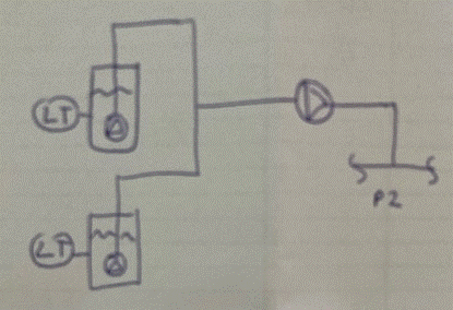
We have a pump configuration as below. Two tank pumps and a booster pump. P2 is fixed pressure. What is a good way to control these pumps?

Tank pumps on level control

Booster pump controls it's suction pressure. But this a packed water line, so will a pressured accumulator be required?
Other control loops options for the booster pump?
Booster pump controls the maximum current draw (or speed) of the tank pumps? no need to even look at the booster pump suction pressure.

There will times when P2 is low and the booster pump is not required. When this happens an NRV around the booster can open.

Screenshot_2022-03-02_104042_Small_y6q0gg.gif
 
Replies continue below

Recommended for you

Lots of questions.

Type of the different pumps?
Flow rates of them
"Tank pumps in level control" what does that mean? Start stop? VFD? Something else?

"Booster pump controls its own suction pressure" How?

What are you trying to achieve? Steady flow? Variable flow from the tanks? Fixed level in the tank?

Remember - More details = better answers
Also: If you get a response it's polite to respond to it.
 
As you have not given any flow rate or discharge pressure limits, we can only assume its a pump continuously at a whatever flow rate and head you can make application. That you can do with the tank pumps on level control on/off, which will pump as long as there's something in either tank. Then put the booster on high and low pressure switches with on/off. Set the booster LO to turn on the pump when the NRV discharge pressure is higher than the tank pump's max discharge pressure (the NRV closes or is closed). Set the HI pressure switch to turn off if it reaches the max design pressure (+) of P2. Size the booster pump such that 1 tank pumping > its min flow rate and 2 tanks pumping is near its max flow rate, being sure that it can make the head or pressure required to inject into P2 at each of those flow rates. The booster will stay turned off until P2's pressure drops to LO. If P2 piping holds enough liquid to feed its clients as the pressure drops, you're OK. If not, you have to have an accumulator to provide that interim flow. Or you have to raise the discharge pressure capacity of all pumps and get the Lo pressure cutoff to a higher setting, so that the pumps will turn on faster and P2 clients will not run out of supply during the time that the booster is off. During the time that P2 is decreasing pressure, but still higher than the tank pump's discharge pressure, I.e. booster pump is off, tank pump recirculation may be necessary, or maybe they can also be turned off until P2 drops below their discharge pressure capacity. That event resets the booster to await whenever P2 gets above tank pump prrssure capacity to turn on again.

If you want something different, you need to tell us if there are any specific pressure or flow rate operating points or limits you need to have.

A black swan to a turkey is a white swan to the butcher ... and to Boeing.
 
Hi , The tank pumps run on VSD to control the tank level, flow is relativity constant. The tank pumps are line shaft pumps the booster pump hoz shaft. Flow say 50t/h from each tank. Tank pump head to 12bar and booster can add another 10 bar. P2 around 18 bar. We can't have stop start flow.

If the booster controlled the booster suction pressure it would use a pressure transmitter and VSD, but not keen on this, as this an incompressible fluid (water) and would need a accumulator on the line.

Back ground, the tank pumps are existing and P2 as increased so the booster is now required.
 
Kevin,

What I meant was what type of pump in terms of PD or centrifugal? If I assume both are centrifugal it works better.

The difficulty when you have a changeable exit pressure P2 is how to control the booster so it doesn't run out of suction and try and drag more out of the tank pumps than they want to give or it backs up the flow.

What sort of differential pressure range are we talking about here for the booster pump? Centrifugals are not good when you have a big range and even with a VFD you can run into all sorts of issues at min speed

I would just add a control valve on the outlet of the booster pump and control it on booster pump inlet pressure.

I don't see why you think it would need an accumulator. Just make sure all the flow and speed changes are quite slow and you should be OK.

Remember - More details = better answers
Also: If you get a response it's polite to respond to it.
 
Looks like you do not need a VSD at all. Flow rate is apparently constant and therefore I suspect so are pressures. The only possible reason I can see for using a VFD is if the tank pumps produce too much flow and/or pressure when running at their rated, constant speed rpm. When everything is constant, that it could indicate the tank pumps are too big and the VFD was installed to get them to run slower, but then they would not be controlling the tank level. Are? the tank pumps running with widely varying rpm now? The VFD may be keeping the level constant, but that's a bit strange, as tanks are usually installed because the flow into the tanks varies, it does go up and down, but having tanks allows you to pump out at a constant rate. In other words, if you have tanks, you should not need a VFD. Tanks are the capacitors of hydraulic systems. They turn flow variation into constant streams. Their levels are supposed to vary. If there's no flow variation, why have tanks.

Why have VSD controlling a suction tank level? All that does is make the pumps run slower and slower until you reach the control level (probably some low tank level), then the control circuit stays hot while the pump sleeps. Flow also stops when the pumps are sleeping. A LSL/LSH does the same, except the pump rpm is not slowed down before stopping and circuits are cold when the pump is stopped. Why do you have to slowly reduce pump rpm, in such a carefully controlled VSD manner? It makes even less sense to use VFD, if the flow is nearly constant.

Adding a booster does not change anything so far, just increases the discharge pressure. If the 18barg maximum discharge pressure does not overpressure P2, there is no need to control it. Again, why VFD? The only reason for a VFD booster is if the booster pump cannot run efficiently somewhere in the range of 12 to 18 barg. Then you might want to size the booster to produce 18bar at rated speed and flow, but slow the booster rpm down when you can inject into P2 at the lower range, say 12 to 15barg. If you will spend a lot of time pumping at inefficient flow rates, maybe you can save some money by using a VFD booster, or a control valve. Look at the efficiency of the pump between 12 and 15 barg. If it is notably worse, and power consumption is high, go for a VFD or CV solution. Otherwise let the booster pump run constant speed.

So far I am not convinced you need VFD anywhere and the simple level and pressure switches will work just fine. Check the energy consumption at flow rates between the 12 to 15b range and decide if its worth it. I dont see the need to control any process variable with VFD or CV, but maybe you can save some power. Neither control arrangement will start or stop flow, as long as there is enough water in the tanks. If you run out of tank water, both types of control systems have no choice but to stop.

The only thing I need to know is
Are? the tank pumps running with widely varying rpm now?
But for now it looks like the VFD is substituting for a simple HL level switch


A black swan to a turkey is a white swan to the butcher ... and to Boeing.
 
@1503-44
Thanks for the input. The flow rate into the tanks varies over a day by +- 20%. The tank's capacity is about 1 min of the inflow. We can not start stop flow in to discharge header, it will upset other parts of the process. Agree a control valves would work and VSDs reduce power use. The tanks pumps are existing and we do not indent to change the tank level control. The booster pump and it's control loop will be new.

 
Correction: the pumps are operating in parallel, not in series.

============
"Is it the only lesson of history that mankind is unteachable?"
--Winston S. Churchill
 
You do not need to change the tank pump control, if that is inconvenient. It was just to let you know that the VFD was a waste of space.

Personally I would add the booster and run it as I described, with PSH/PSL set to 18+ and 12 bars. It will turn on at 12bars and pump continuously until P2 pressure drops below 12b, where the tank pumps can inject into P2 all by themselves. The PSH cutoff is actually only a safety feature and only needed if the addition of the booster pump's pressure can go above the operating limits of P2. If it cannot, the PSH is not really needed at all. Quite a simple control system. Flow never stops.

Then you can experiment with turning off the VFD too. I would be surprised if you need it, as the tank pumps must apparently run all the time. Let them do it by themselves. If the tank level goes nuts, turn it back on.

A black swan to a turkey is a white swan to the butcher ... and to Boeing.
 
It's confusing - if there is only 1 minute of capacity in each tank then at -20% input they would run dry in 5 minutes if they started filled.
 
Good comment 3DDave.

Typically the tanks in a scenario like this have 5 minutes retention. If my numbers are correct, the tank is approximately 220 gallons capacity. Surely the poster can afford an appropriately sized tank.

 
If you can justify VSD on booster to save on power, suggest:
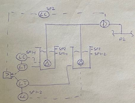
1. Operate tank pumps as existing on level control at each tank acting on tank pump
2. Run the booster on flow controller (acting off FT on booster discharge) (which then acts on booster VSD) as a slave to new high level master controller acting off the current LTs' at each tank. Use a high level selector to feed the new high set master LC in DCS.

This way you wont need to look at booster suction pressure.

Other schemes also may be possible also, but this is what comes to mind at the moment. This scheme will also enable the booster to go to min speed ( while tank pumps do not slow down) and allow the suggested bypass NRV to open when delivery line pressure is low. See attached controls sketch

What do you do now when downstream user trips - how do you cut off inflow to tanks?
 
 https://files.engineering.com/getfile.aspx?folder=2ee8aeea-28a0-4ed6-bc66-baef8f50889e&file=2ndMarchyr2022scan01.jpeg
Kevin,

Looking back at this you're giving us conflicting / changing information which doesn't help us.

So a the start you say

"P2 is fixed pressure."
But then you say
"There will times when P2 is low and the booster pump is not required"
That is really quite difficult for a pump to vary between say 0.5 bar diff pressure and 6 bar (18 bar - 12 bar coming from the tank pumps)
So which is it?

Even with a VFD you won't get that level of change. So the alternative is simply a fixed speed pump and a control valve to maintain a fixed inlet pressure regardless of pressure P2. It's not clear how you could switch from booster pump operation to not working and vice versa. You would then need a pressure switch to turn the booster pump off and let it flow past the NRV.

Your booster pump might be better off being a PD pump which only really cares about flow and controls speed on inlet pressure? I.e it takes away everything the tank pumps can throw at it, but not more....

Remember - More details = better answers
Also: If you get a response it's polite to respond to it.
 
This has gotten way overcomplicated. 3 (or 4) pressure switches [full stop]].

A black swan to a turkey is a white swan to the butcher ... and to Boeing.
 
@littleInch

During normal operation P2 is high and the booster pump is required. P2 line pressure controlled by another part of the process. At times (not often) P2 may drop and the booster is not required.

@georgeverghese

I like your thinking. Seems better for a process where we want steady flow response. At least one of the tank pumps would run at full speed, while the booster does enough to keep the highest tank level under control.

Screenshot_2022-03-04_112908_ali0je.gif
 
Yes, you've got the hang of it now. LC resetting FC on the booster may be smoother as I've shown on my sketch.
You havent told us much about what goes on the end of this line downstream of the booster. If demand at this user is transiently lower than what is delivered by these pumps and a valve chokes inflow at this user, the pumps upstream would all deadhead. Can the line handle full deadhead pressure? If not, a pressure controller would be required at the upstream end of this delivery line to cutout the output of the FC at the booster (via a low signal select) to limit booster speed, and as a consequence of this, a min flow recycle line would be required at the common line d/s P1 and P2. Min flow recycle controller setpoint should be calculated continuously in DCS to account for the number of pumps in operation and the current operating speed of the pumps.
 
Sorry, can't resist a few more comments.

You need to think and completely understand what LittleInch is trying to tell you about sizing the booster pump for operating with a VFD. You want 12 to 18b range, but are more likely to have to deal with a 12 to 28bar discharge. If you additionally attempt to control that 28b to 18, you wind up not using half the operating range of the pump you need to select. If you chose a booster pump to give you 18b discharge at full speed, you only get 4.5b running at half speed. 3/4 speed only gets you 10b. Why run that on vfd when basically it will always be operating at 80%+, that's constant speed pump territory. I also think that there will be mismatches between tank pump flow and optimum vfd booster flows that will not allow the booster to run efficiently.

Controlling it by its suction pressure? That's only needed because your tank pumps have a vfd and will probably cause booster suction to vary. VFD over VFD is like back to back control valves. Neither really controls anything, end result, they controlling each other, or needlessly compensate for what the other is doing.

If you do not understand that the PSL/PSH provides uninterrupted flow, you don't understand nearly enough to make any decision between the two options.

VFD on top of VFD is not a good solution. You will be taking what should be a simple solution and turn it into something that will require you to do a full dynamic simulation to prove it will have any benefits whatsoever over the simple PSH/PSL. And yes, you may further need to add booster pump discharge pressure control (not flow control), if your discharge pressure is higher than P2 capability.

It seems to be a simple water supply system, not a chem plant or refinery. Where are these complicated control systems coming from? Completely OTT IMHO.

A black swan to a turkey is a white swan to the butcher ... and to Boeing.
 
@1503-44

"Why run that on vfd when basically it will always be operating at 80%+, that's constant speed pump territory. I also think that there will be mismatches between tank pump flow and optimum vfd booster flows that will not allow the booster to run efficiently."

I would like to point out that IF the pump "constantly" runs at a specific speed then VFD is worthless - but IF you need 100% but often runs at say 80% then a VFD will save on your energy bill. E.g. running at 100% 10% of the time and 90-80% pump speed) 90% of the time will save you about 30% energy. Furthermore, VFD are excellent for flow/level control in many cases better that constant speed and CV. However, more cost on maintenance and CAPEX of course. The calculation holds a lot of assumptions of course.

BTW agree on "VFD on top of VFD" is not a good idea, but thats true for most cases of installing control elements in series. They are often acting "against" each other.

Best regars, Morten

--- Best regards, Morten Andersen
 
80% speed is a pretty good break even point. I usually find that a constant speed pump's efficiency running at 80% flow (with valve) is economically comparable to a vfd controlled pump running at 80% speed, especially when adding the extra costs of vfd power supply, extra space, wiring and extra maintence. At 70% speed a vfd usually has a clear advantage, but can still be less efficient if there is a variable flowrate and you do not spend a lot of time pumping at rates below 75%. If you spend more time operating at 80-100% than you do at 60-80% speed, then the pump with control valve is usually better.

Other considerations

If its not a question of economics, it can amount solely to the system characteristics. If there are wide changes in either pressure or flow rate, a vfd can be great to have, but if you are feeding to a boiler at preferably constant rate and pressure, a lot of any advantage is defeated. A variable control device works best with the need to control something that varies, A discharge flow rate or pressure that need to vary between 0 and 100% is a good reason. 50-100% useless; you need a smaller pump.

Controlling suction pressure; useless. A pump can pump if it has NPSHr. If it doesn't, a LSL is all you need to control that. A vfd will not make more flow available to suction than what is in the pipe, a tank or a lake, although a vfd to control lake level, maybe could have some purpose, but then you are not controlling pump suction pressure, you're controlling a variable lake level.

There is also not much advantage to having a vfd controlling flow, if you have adequately sized tanks(, or a lake). Even less sense is having a vfd to control tank level. Tanks are there to change variable input into constant flow output, or constant input to batched outflow. They do that by changing their level. Why hold them at constant level. In that case a vfd defeats the purpose of having tanks and having tanks defeat the purpose of having a vfd.

I like to have controls that make sense.

A black swan to a turkey is a white swan to the butcher ... and to Boeing.
 
Status
Not open for further replies.
Back
Top