Continue to Site

Eng-Tips is the largest engineering community on the Internet

Intelligent Work Forums for Engineering Professionals

  • Congratulations waross on being selected by the Eng-Tips community for having the most helpful posts in the forums last week. Way to Go!

Taper lock / taper pin fastener in cast metals

Sep 27, 2024
11
Regarding taper lok / taper pin type fasteners in aerospace applications;
Can anyone confirm it would not be prudent to use such fasteners thru investment castings made of aluminum and or cast iron materials loaded predominantly in shear.
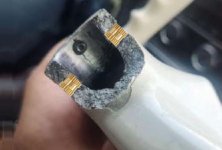
In particular, tubular shapes of relatively thin wall thicknesses. Effecting a single precision tapered / reamed hole in such material and specific configuration, could not / would not maintain the controlled interference fit expected / required over time. In this case, stress corrosion fatigue and eventual fracture of an investment cast aluminum flight yoke integral stub boss secured to a cres steel tube via a single taper pin and nut. Cres tube slip fits inside the flight control yoke stub boss. The fractured off stub exhibits an axial stress corrosion crack (grain dark gray to black in color) emanating from the I.D. of the boss
on one side of the radial fracture terminated by overload brittle fracture ( grain light gray color) on the other side.
Dissimilar metal corrosion
is also suspected as the taper pin and it's nut remained attached to the cres tube and exhibited loss of cad plating thru out most of its mating surfaces. Additionally, it seems re-torquing the taper pin nut over many years so as to maintain interference fit and thereby eliminate cumulative "play" would tend to expand the stub end cast metal beyond its Fcy property. I could not find any guidance / standards in any publications so far, including Boeing's taper shank fasteners in aluminum structures, documemt# 6m54-153, McDonnell Douglas process standards (DPS), Michael Niu's publications, NASA. Thank you.

 
Replies continue below

Recommended for you

Ugh, that set screw photo shows a horrible condition.

And since when can (supposedly certified) airplane parts be bought off eBay??? And people are complaining on the Mooney forum "that the replacement yoke has no airworthiness documentation". Yet they will buy 50+ year old junk off eBay and merrily have it installed.

Fred, my suggestion as you outlined above might work, but all of the previous failure modes and associated ADs should be reviewed to be sure the solution will adequately address all of them. Including whatever function that horrible looking set screw mess was supposed to do. That probably should be eliminated.
 
The friction increase set screw feature fiasco is there to further eliminate cumulative control yoke to CRES tube end play/slop in service, over time.
Condition is/was exacerbated by single (1ea) taper critical ream out process either deviated from or the result
of poor execution/workmanship.

This less than sub-optimal design was Mooney Aircraft Co's economically cheapest securing solution then and would not pass muster today from an engineering and or FAA certification aspects. Mooney more than likely never envisioned then none of their earlier machines would still be in the air 45+ years later.

Flight control yoke assembly, CRES tube end failure due to fatigue crack(s) emanating from the tapered holes and or divot in the O.D. of the CRES tube created by the subject set screw became subject of AD 77-17-04, making Mooney aircraft SB M20-250B mandatory by repetitive inspections until such time tube(s) yoke end is either modified per SB instructions or tube(s) are replaced by next higher part number featuring i believe thicker wall thickness and constituting AD's terminating action. The cast aluminum yoke was not at issue then.

SB M20-250 truncates the crack damaged tube end and replaces the end by a machined telescoping sleeve to
nest inside the CRES tube I.D., restoring the tube's integrity and original lenght. The sleeve is secured to the CRES tube by two (2) radially oriented and equally spaced fasteners (bolts/nuts assy). The repair sleeve is drilled out and taper reamed off the existing tapered holes used as locating template in the cast aluminum yoke.
Free hand drilling and reaming will defeat the entire process unless a secured to tube type custom drill / ream jig is available.
Absent a jig, removing the CRES tube to a shop, securing the work in a mill is essential and critical for the end results required/expected.

A combination of SW composites suggesting a filler plug either separate (at least drift fit in lieu of slip fit; my error) or integral to the machined telescoping sleeve, deleting the set screw and sleeving the end of the tube per SB along with precise executions would meet the expectations for a rigid join and may buy owners another 40 years!

3DDave, no sir, i do not do what i want. We engineer it first with all due dilligence required of our trade and safely
fix it right the first time.


What do you want? You want the same hole, the same shaft, the same yoke, and a magic change to the fastener.

Who is "we" and what engineering are "we" doing?
 
I like how they have to remind those performing this service not to drill through the electrical wires in the shaft.

It does require drilling multiple extra holes in the control shaft and less than ideal contact between the bushing retaining bolts and the control shaft. The bolts are to be .186 to .189 and the holes .190 to .194, so up to 0.008 of slop on a (rough guess) 0.63 radius or less - up to almost one degree of play. Did shaft locking compound existed back then to keep that bushing from working back and forth? I bet it cannot be used even now because the FAA won't allow it.

I think the control wheel killer mentioned by the Mooney owners is that "reinstall taper pin" in the un-numbered step item "b" that has the opportunity for Bob Bicep to go to town on the taper pin retaining nut and ensure the taper pin doesn't come loose. However I don't know if there have been broken control wheels on this adapter bushing.

Jigs and fixtures would be most handy if the intent was to allow owners to shift parts between planes after this, but this makes for custom installed parts that won't sit right on any other aircraft. This cuts into the secondary parts market for what appears to be a problematic design.

I noted a number of owners comments bemoaning that they could get new control wheels CNC'd from billet to a matching shape or some shape they liked even better that would have superior properties if only there was paperwork that said the better parts were allowed by the FAA.
 
"I like how they have to remind those performing this service not to drill through the electrical wires in the shaft."

And yet they are trusted without a reminder to remove the chips and swarf......

It's hard to drill a hole perfectly on the diameter of a shaft. Even harder two concentric shafts that aren't in any way constrained relative to each other. Harder still to do it twice. So a drill fixture might be nice. And even a wrap of tape to hold the bushing sort of in place while drilling would be better than nothing.

As a child I build a gas powered go cart from a battery powered kiddie car. It was pretty fast (and didn't have much in the way of brakes).

The steering wheel broke and I didn't have a replacement, I just clamped a pair of Vice-Grips to the steering shaft.

If I had a Mooney S30 I'd want a set of Vice-Grips in the cockpit.
 
Apparently the affected aircraft have dual control; the backup is located in the next seat, or as one commentor said, parphrased, "I just flew it like a side stick aircraft."
 
CAUTION. Are You sure the control yoke is cast aluminum? Designers/manufacturers have a maddening pursuit for weight savings... often yokes are made from cast magnesium alloys... which is often mistaken for cast aluminum.

Cast Al/Mg 'yokes' are on many of the older GA designs... and even many 'heavies'. I think most will experience general 'looseness' of the control tube fasteners at the attachment sleeve-to-tube... or corrosion... resulting in 'sloppiness/wear' which is the usual first-indicator that 'sompin needz fixin'... before it breaks off. A taper pin thru Al/Mg casting-to the SStl control tube to the casting can never be tightened too severely to the casing-sleeve [taper-reamed-thru], since the pin will effectively 'jam' in the stronger/stiffer SStl control-tube wall. Casting hole-wear will generally loosen the Yoke FIRST.

Comments...

Notice that the electrical wiring didn't fail... and kept the yoke from falling to the floor. I am always amazed how EE/EL-harnesses and flight-control cables [wire-rope] often 'hold aircraft sections together' during horrible crash-impacts.

War-Story. This sounds familiar... in a dreadful sense. I worked O-2A/Bs... Military version of the Cessna 337 SkyMaster... for several years. Crashes were all-too-common.

In the early 1980s, an O-2A pilot was on a 30-degree rocket-pass dive. When he went to pull-out, his control 'yoke' failed just like this Mooney 'yoke'... where it attaches to the control tube. Somehow the pilot had sensed something was 'off' about his 'yoke' at the last second before it failed... and had the survival instinct to reach across the cockpit and grab the right-side control 'yoke'... and was able to pull-out of the dive and land safely. DAMMMM. The O-2A was 'hand-flown' rather abusively on a constant basis... from the left seat... so obviously the LH yoke was destined to be-the-one-that-fails.

Many aircraft never experience such abuse... due to the use of autopilots and/or precise 'trim' for cross country or routine low-stress training/practice/local flights.

Regards, Wil Taylor
o Trust - But Verify!
o For those who believe, no proof is required; for those who cannot believe, no proof is possible. [variation, Stuart Chase]
o Unfortunately, in science what You 'believe' is irrelevant. ["Orion", HBA forum]
o Only fools and charlatans know everything and understand everything." -Anton Chekhov
 
Mint, the set screw was probably the original design. The taper pin is the new design. The taper pin could be retrofitted into an existing set screw yoke. Newer yokes may not have the set screw at all.

They've gone from a yoke that may loosen and slip to a yoke that splits in half. I can see over tightening the nut easily splitting the yoke as it has a thin wall.

Taper pin holes are matched so swapping a yoke to another shaft would require reaming the two parts together.
 
TugboatEng said:
the set screw was probably the original design.

Crap, I hope not. I can't imagine anyone ever thinking that "we'll just grunge down a setscrew on a thin-wall tube and call it good" as working for a flight-critical control connection.

My guess is that the setscrew is there to take up the play in the loose and variable fit between the shaft and the hub.

I think the yoke came with the tapped setscrew hole and a pilot hole for the pin.

Slip the yoke over the shaft.
Tighten the setscrew to shove it all the way to the side.
Match drill and ream through the hub and shaft.
Install the taper pin.

"Design for maintainability" wasn't a thing back then.
 
You have no idea how often I see setscrews in an opposed condition. Are there rules forbidding this in aerospace? I don't know. Are some engineers ignorant enough to do this? Absolutely! Does this apply in this scenario? Not entirely. However, there is a general misunderstanding of how setscrews work amongst engineers. The biting of a cup point should not be the primary mode of force transfer. Friction should always be. I agree that a set screw against a thin wall tube is also not a good design.

How often does this need to be disassembled?
 
It'll better to add brass thread inserts while aluminium casting, to increase the force around screw, and to avoid stress whilre driling and tapping.
Brass thread inserts
 

Part and Inventory Search

Sponsor