Continue to Site

Eng-Tips is the largest engineering community on the Internet

Intelligent Work Forums for Engineering Professionals

  • Congratulations KootK on being selected by the Eng-Tips community for having the most helpful posts in the forums last week. Way to Go!

Tapered I-Section Verification

Status
Not open for further replies.

Accumulated

Structural
Nov 30, 2017
16
Hi Eng-Tip-ers,
I've got a tapered I section for verification check as shown in the attached picture against Eurocode. There is not up-lift nor moments being transferred from top of the flange. All of the loads are in compression and shear.
1) How do I go about checking the web in buckling and tranvese strength when you have varying height of the web?
2) How would the effective length of web in compression be calculated when the web is cut off at an angle?
3) Would all the shear from top flange be resisted by the bolts and flange being check against bearing? Is shear check in web necessary?
3) What other necessary checks are needed for this sort of situation?
4) Is there any good guidance or reference book?

Thanks in advance.
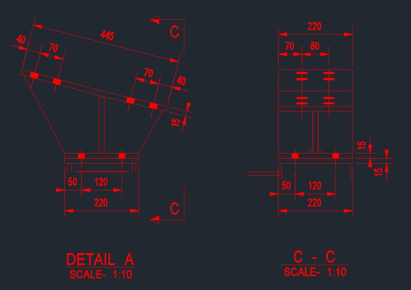
asdf_nctmv1.png

(N.B: I'm still a graduate learning and never dealt with tapered sections before.)
 
Replies continue below

Recommended for you

Anyone?
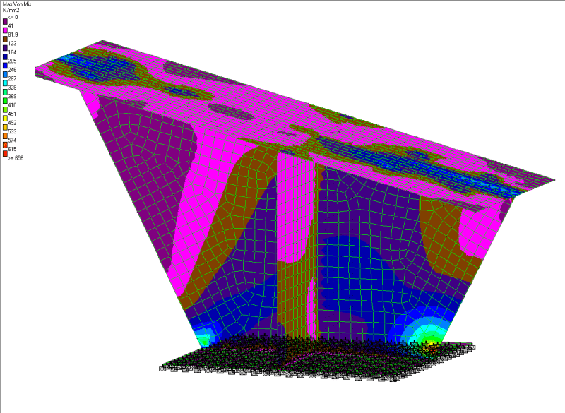
(I tried to do a FEA. It is showing that the web has yielded at the cut out where it meets the bottom flange. I think I'm modelling it wrong.)
 
what cut-out ?

have you tried free body diagrams ? to understand the reactions at the base and at any section (cut) thru the fitting.

another day in paradise, or is paradise one day closer ?
 
rb1957 said:
what cut-out ?

See the attached picture.
FEA_ypyk9a.png

rb1957 said:
have you tried free body diagrams ? to understand the reactions at the base and at any section (cut) thru the fitting.
I don't quite get what you mean. Nevermind. I'll try it.
 
That's the problem with using FEM for connection design. You usually get localized stress risers. The reality is you get a little localized yielding in those locations and then the load spreads out over a wider area.
 
@JoshPlum Am I modelling it wrong? I have considered the base as fixed where as it in going to be sat on top of a steel column. I think fixed support condition on the flange is causing the problem?

Would you not recommend using FEA for connection designs? Or is this one of those times where we have to use engineering judgement to know it wouldn't act that way in real life?
 
You should always be using your engineering judgement in conjunction with your FEA analysis. Its not so much that it won't act like that in reality, but the question is - does it matter if you get a bit of local yielding as the model shows?
 
You're not necessarily modeling it "wrong". But, FEA is not reality. Your results are probably based on a linear elastic analysis. It probably represents what would happen if non-linear behavior didn't occur. No localized yielding at high stress locations. No force re-distribution due to localized yielding. No bolt slip. No plate buckling. Heck, the plates are 2D elements. Load applied to one surface doesn't "spread out" through the thickness of the plate.

In my opinion, you'd be better off doing classic hand calcs for this connection design. Even if that meant you didn't consider the taper of the section.
 
I'm concerned about all those possible constraints on the lower face ? Is it bearing against a surface ? so many constraints (rigid or flexible ?) seem like a likely source of "unreality". Maybe that face has a few fasteners in it, and the gap elements (like you really want) to control the surface contact/gapping ?

another day in paradise, or is paradise one day closer ?
 
Accumulated - JoshPlum is correct about the small areas of high stress yielding and shedding stress to other adjacent areas.

If you don't understand this concept - then you shouldn't be interpreting your model, and designing from it, without help from someone who does.


Check out Eng-Tips Forum's Policies here:
faq731-376
 
yeah, but I suspect poor modelling of the support of the lower face is the cause of the high stresses in the web.

agreed, we could say "localised yielding ... linear FEA ... load redistribution" and show it good with a hand calc; but a poor model is a poor model (if my understanding of the limited view we have of the model is correct).

another day in paradise, or is paradise one day closer ?
 
I've got to agree with rb1957, perhaps put some springs and play around with the stiffness and I think you will see the higher stresses filter out into the rest of the supports which you would expect with some limited deformation of the support surface. I bet if you review the reactions you will see virtually no force spreading out laterally from the flange at the base and along the web. All you are trying to verify here is that the higher stresses with some judgement/applications of first principles are in fact lower than your crude model.

 
Infinitely rigid boundary conditions do wreak havoc on stresses and are not very realistic so Agent666 and rb1957 are spot on.

Check out Eng-Tips Forum's Policies here:
faq731-376
 
Cheers everyone! I will get cracking on. I will post back if I have any further questions. Meanwhile, Can someone answers regarding hand calcs?

1) How do I go about checking the web in buckling and tranvese strength when you have varying height of the web? (i.e; which height to use? Min height, Max Height, Intermediate height?)
2) How would the effective length of web in compression be calculated when the web is cut off at an angle?
3) Would all the shear from top flange be resisted by the bolts and flange being check against bearing? Is shear check in web necessary? (i.e; I'm thinking all the shear would be resisted by the bolts and flange.)
3) What other necessary checks are needed for this sort of situation?
4) Is there any good guidance or reference book?
 
You could look at it like a gusset plate per AISC design guide 29 - particularly a chevron gusset analysis.
 
Status
Not open for further replies.

Part and Inventory Search

Sponsor