Greatone76
Structural
- Feb 2, 2006
- 64
I am working with steel street light poles. They are a round section that tapers down from a larger section at the bottom to a smaller section at the top.
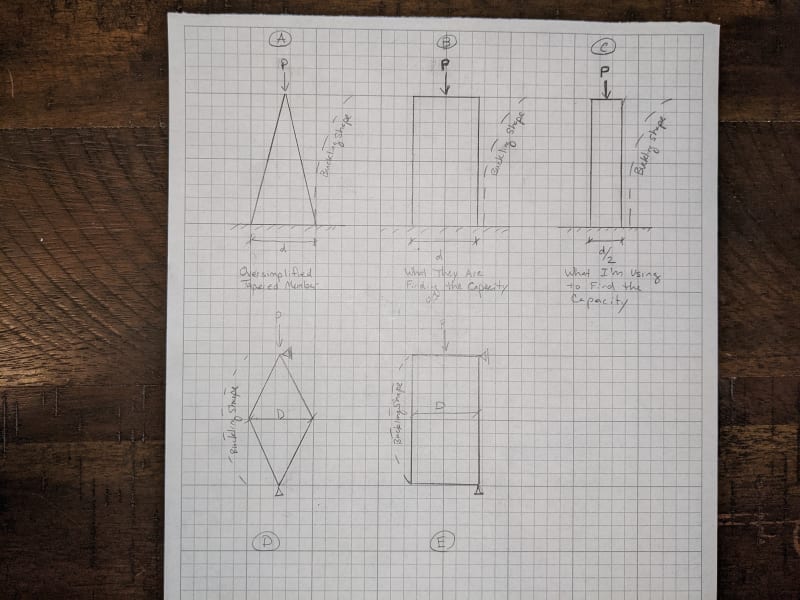
For the overall compression capacity, we use the entire height of the columns and we use the properties of the pole at the mid-height of the pole. Since these are tall slender members Euler Buckling of the overall member is what is going to control the design, the slenderness/capacity is highly dependant on the height of the member and radius of gyration.
We use the mid-height radius of gyration based on the AASHTO LRFD Specifications for Structural Supports for Highway Signs, Luminaires, and Traffic Signals (2015 version). C5.10.2.1 - says that using the radius of gyration at a distance of 0.50L is conservative for all tapered light poles.
For one particular example, I'm working with I get a compression capacity of around 2000 lbs for the pole. When I use that value and put it in the combined forces equation I have the pole as 1.2 utilization and have requested that my client utilize the next thicker pole gauge.
The pole manufacturer is pushing back and saying that utilizing the client's custom equipment on the pole that the currently proposed pole is acceptable. With that fact I requested the calculations in order to understand where they were getting their values and where our differences were.
Upon review of their calculations, I saw that we agreed on moment capacity, shear capacity, and torsion capacity, but their compression capacity was much larger than mine. Upon detailed review, it turned out that they were using a much larger radius of gyration nearer to the base of the column to get their compression capacity. Their capacity was around 7000 lbs. So they had utilization of 97%.
I wrote back to my client and informed them where I see the difference between my calcs and theirs and said while I understand that my mid-height radius of gyration may be conservative and I could justify a different value if they would provide an engineering reference I would be happy to adjust mine upward to match theirs and would change my calcs to agree if they could provide a reasonable reference for the higher radius of gyration value.
The manufacturer responded back that they divide the pole up into sections and check the capacity at the base of these different sections vs the loads. And for compression capacity, they use the properties at the bottom of the section and the height from the bottom of the section to the top of the pole. So at the mid-height, they use the radius of gyration at the mid-height and the height of the pole as half the height of the overall pole. So at the bottom, they confirmed they use the base radius of gyration and the whole height of the pole. Which I believe is not acceptable. To me, this would assume the whole height the column is buckling over is the largest section at the base transferred all the way to the top.
Question A - Am I correct in my thinking that using the base radius of gyration is completely inappropriate? Am I missing something about the pole being cantilevered from the base (fixed base fee top) and due to the shape the buckling happens mostly at the base, so the is appropriate?
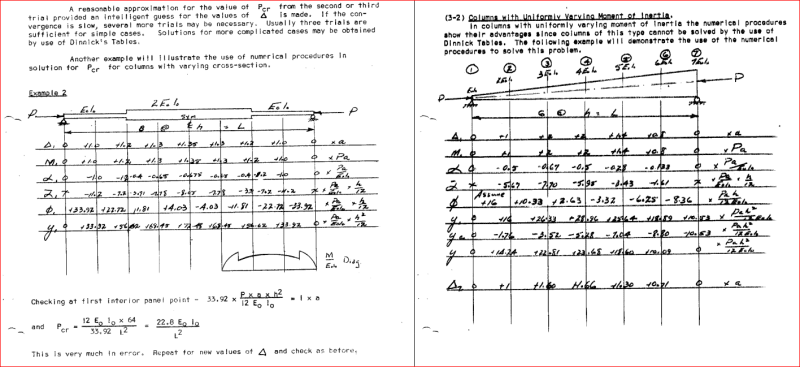
Question B - Does anyone have a reasonable engineering reference where I can better utilize the 2/3 point of some other situation to get a reasonable higher value of the radius of gyration for a tapered round pole?
Question C - Any advice on how to handle the situation when communicating back to the client and manufacturer?


