Continue to Site

Eng-Tips is the largest engineering community on the Internet

Intelligent Work Forums for Engineering Professionals

  • Congratulations SSS148 on being selected by the Eng-Tips community for having the most helpful posts in the forums last week. Way to Go!

Tappered Round Columns 2

Status
Not open for further replies.

Greatone76

Structural
Feb 2, 2006
64
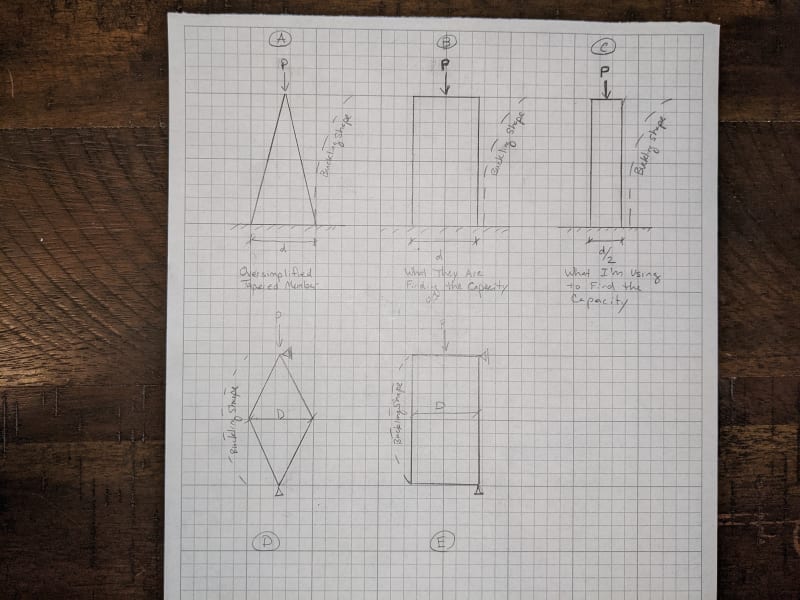
I am working with steel street light poles. They are a round section that tapers down from a larger section at the bottom to a smaller section at the top.

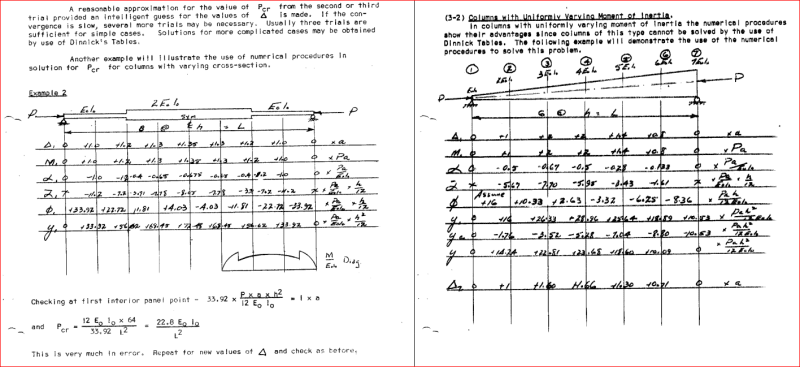
For the overall compression capacity, we use the entire height of the columns and we use the properties of the pole at the mid-height of the pole. Since these are tall slender members Euler Buckling of the overall member is what is going to control the design, the slenderness/capacity is highly dependant on the height of the member and radius of gyration.

We use the mid-height radius of gyration based on the AASHTO LRFD Specifications for Structural Supports for Highway Signs, Luminaires, and Traffic Signals (2015 version). C5.10.2.1 - says that using the radius of gyration at a distance of 0.50L is conservative for all tapered light poles.

For one particular example, I'm working with I get a compression capacity of around 2000 lbs for the pole. When I use that value and put it in the combined forces equation I have the pole as 1.2 utilization and have requested that my client utilize the next thicker pole gauge.

The pole manufacturer is pushing back and saying that utilizing the client's custom equipment on the pole that the currently proposed pole is acceptable. With that fact I requested the calculations in order to understand where they were getting their values and where our differences were.

Upon review of their calculations, I saw that we agreed on moment capacity, shear capacity, and torsion capacity, but their compression capacity was much larger than mine. Upon detailed review, it turned out that they were using a much larger radius of gyration nearer to the base of the column to get their compression capacity. Their capacity was around 7000 lbs. So they had utilization of 97%.

I wrote back to my client and informed them where I see the difference between my calcs and theirs and said while I understand that my mid-height radius of gyration may be conservative and I could justify a different value if they would provide an engineering reference I would be happy to adjust mine upward to match theirs and would change my calcs to agree if they could provide a reasonable reference for the higher radius of gyration value.

The manufacturer responded back that they divide the pole up into sections and check the capacity at the base of these different sections vs the loads. And for compression capacity, they use the properties at the bottom of the section and the height from the bottom of the section to the top of the pole. So at the mid-height, they use the radius of gyration at the mid-height and the height of the pole as half the height of the overall pole. So at the bottom, they confirmed they use the base radius of gyration and the whole height of the pole. Which I believe is not acceptable. To me, this would assume the whole height the column is buckling over is the largest section at the base transferred all the way to the top.

Question A - Am I correct in my thinking that using the base radius of gyration is completely inappropriate? Am I missing something about the pole being cantilevered from the base (fixed base fee top) and due to the shape the buckling happens mostly at the base, so the is appropriate?

Question B - Does anyone have a reasonable engineering reference where I can better utilize the 2/3 point of some other situation to get a reasonable higher value of the radius of gyration for a tapered round pole?

Question C - Any advice on how to handle the situation when communicating back to the client and manufacturer?
 
Replies continue below

Recommended for you

To be honest I'm surprised that the utilisation would come anywhere near 100% for a light pole. What sort of street light pole weighs 7000 lb?

If it were me, I would come up with a quick FE model using the tapered properties of the pole and distributed loads and calculate the elastic buckling load. Then maybe try to convert that to an equivalent uniform section for the whole pole.
 
The moment at the base is the majority of the capacity, The compression capacity plays a role in the overall as they are so small because they are long slender members. A typical light pole (actual pole, street light, and misc. attachments) with the client's custom equipment is around 800#. So the load is a relatively large percentage of the capacity. Me using 40% of the capacity vs them saying they are using 15% of the compression capacity is the difference in our calcs.
 
Question A - Am I correct in my thinking that using the base radius of gyration is completely inappropriate? Am I missing something about the pole being cantilevered from the base (fixed base fee top) and due to the shape the buckling happens mostly at the base, so the is appropriate?

Yes, this seems inappropriate to me. I don't want to say that it's flat out wrong. But, absent a code reference justifying this assumption, it sounds unconservative.

Question B - Does anyone have a reasonable engineering reference where I can better utilize the 2/3 point of some other situation to get a reasonable higher value of the radius of gyration for a tapered round pole?

The company I used to work for (RISA) purchased a program called ERITower, which we then renamed RISATower. They eventually sold it to one of RISA's developers (Peter C) who changed the name again to TnxTower. It had a really good analysis module that was based on the TIA code (which relates to cell phone / communication towers). A lot of these towers are "tapered monopoles". I would personally feel pretty comfortable if the TnxTower program said that this monopole was okay. Not cheap, but worth getting if you're doing a lot of these types of towers. There are other programs (PLS Tower sp?) that do similar things, but I don't know much about them.

Also, I'm only familiar with the F and G versions of the TIA code. If you have a copy of the latest H version of the code, then this might give better information.... Though, my impression is that this code is leaning more and more towards complex (or 2nd order) analysis of these slender structures and less on hand calcs.

Alternatively, there are two methods of analysis that I might look towards:
1) Use AISC's direct analysis method in a program that is capable of doing 2nd order analysis. But, make sure to use multiple members to model the taper in this pole.

2) There is a method of analysis discussed in AISC's design guide 25 for non-prismatic (i.e. tapered) members. I believe this is Appendix A. It gives a method of determine the Buckling Factor of a given loading condition on a tapered member. I think Timoshenko's book may have this method as well. But, I found this design guide to be easy to follow.

I once put together an Excel file that did this "method of successive approximations" to calculate the buckling of a tapered wide flange column. If you're desperate, let me know and I'll dig through my hard drive to see if I can find this file.... Though I warn you, you'll want to have the AISC design guide to understand what I've done.

 
Greatone76 said:
Question A - Am I correct in my thinking that using the base radius of gyration is completely inappropriate? Am I missing something about the pole being cantilevered from the base (fixed base fee top) and due to the shape the buckling happens mostly at the base, so the is appropriate?

JoshPlumSE said:
Yes, this seems inappropriate to me. I don't want to say that it's flat out wrong. But, absent a code reference justifying this assumption, it sounds unconservative.

I disagree that this seems wrong or unconservative. We are talking about a tapered pole that cantilevers up from the base. Their approach is essentially breaking it up into multiple sections and analyzing it at each section to check the capacity. If they only checked it at the base then I would say there could be a problem, but if they are checking it at each section as stated I don't see that they are missing anything (provided sections are a reasonable length)

Greatone76 said:
To me, this would assume the whole height the column is buckling over is the largest section at the base transferred all the way to the top.
You are combining the compression force with the bending moment at this point right? You are using the cross section of the pole at this point to calculate the moment capacity and analyzing the stresses at that point. It seems to make sense that you would also use the properties of the pole at that point to calculate the compressive capacity. Then you would move up a few feet and make the check again. The cross section of the pole goes down so your overall capacity decreases, but your bending moment demand also decreases so it usually checks out.
If the sections are on the longer side and argument could be made to use the r from the midpoint of the section being analyzed rather than the base, but if the sections are sufficiently short, I don't see this changing much.

This approach may not be appropriate for a non-cantilever situation, but I am having a hard time seeing why it wouldn't be appropriate here (assuming a second order analysis).
 
dauwerda said:
I disagree that this seems wrong or unconservative. We are talking about a tapered pole that cantilevers up from the base. Their approach is essentially breaking it up into multiple sections and analyzing it at each section to check the capacity. If they only checked it at the base then I would say there could be a problem, but if they are checking it at each section as stated I don't see that they are missing anything (provided sections are a reasonable length)

The problem, as I see it, is calculating the Elastic Buckling Strength of the tapered member. This depends on a few things:

a) Member cross section: Since this changes with the height, the typical formulas for calculating this do NOT apply. They might give you some "ball park" figure. But, it's no where near as accurate as it would be for a prismatic column.

b) Loading: Most of the time, we assume a member is loading under constant compression. That's certainly what our Euler Buckling formulas in AISC assume. This has never been 100% true, but it's good enough for columns that are loaded primarily at story heights. For cases, where the load varies significantly along the height, that's not a good assumption. Tapered monopoles for communication towers tend to fall in this category of varying load with height.

Because of these two things you need to do one of the following to get an accurate estimate of the Euler Buckling Strength of the column. This is not my list, rather this comes from the AISC design guide for non-prismatic (i.e. web tapered) members.

1) You can use a software that is capable of doing an "Elastic Eigenvalue Buckling Analysis".

2) You can use the "Method of Successive Approximations" (Timoshenko and Gere 1961)

3) The elastic buckling strength can be approximated pretty accurately for a column with a constant, linear taper and constant axial load using the formula provided in the design guide:

Pel = pi^2 (E*I_prime) / L^2.

Where I_prime is the moment of inertia calculated using the depth at 0.5*L(I_small / I_large)^0.0732.​

The only issue I see with using this formula is that it was empirically derived for tapered wide flange sections. I have no reason to believe that it would not work for Tapered pipes or polygons. Regardless, I'd say that this formula is significantly better than using the base moment of inertia.
 
Seems odd to me that a cantilevered light pole would have 40% of it's capacity used up by axial loading.

And I agree w/ dauwerda. It doesn't seem unreasonable to use the section properties at the height under consideration.


I would agree with the above. But I would suggest that, for a gentle tapering monopole, the checking each section approach would end up with a pretty close answer though be slightly unconservative.

I'd expect that the base would be the critical section and checking other points is just to check you are not tapering too fast. However working out the Euler buckling of the base based on the moment of intertia of the base should be obviously unconservative (even it only mildly unconservative).

At a complete guess I believe you could likely get a value of the "effective moment of inertia" by back calculating it from a calculated deflection from a nominal value. To calculate the deflection under a nominal value is still a bit of a chore doable and any computer package could do it rapidly. If this was my problem I'd do it like this and use it as a check for a value I determined using elastic eigen value buckling analysis.

The problem really is almost identical to this column with obviously different effective length:
1024px-Sidney_Myer_Music_Bowl_16.09.18_g67eg0.jpg

This was built in the 50s.
 
PXL_20211209_220521779_1_prlbke.jpg


First off we are only talking about column compression capacity. I understand and agree sections along the length make sense and work for the moment, but for compressions sections, I don't think you can use the properties at the base of the section to pull a compression capacity for a member that is slender and the overall buckling of the member is controlling the capacity.

Oversimplifying the situation and we say we have a triangular-shaped cantilevered column (attached sketch A).

To me, they are taking that base of the column and projecting that section all the way to the top, and using that full section to get the capacity of the column (attached sketch B). The overall buckling happens over the entire length of the column, so assuming it is the largest possible section from top to bottom seems very unconservative. You are basically giving the entire member a much more rigid property than it actually has.

My basic assumption backed by the code comment is to use the section property at half the height of the column so at the top half I'm stiffer, but at the bottom half, I'm less stiff (attached sketch C).

I compare the situation to a standard pinned column tapered member where the largest section is at the middle and you telling me that you are going to use that mid section's largest stiffness to get your capacity and I see that as completely incorrect. (Attached sketch D and E).

Please explain what I'm missing or how I'm seeing this wrong that for a tall slender column where the overall buckling of the column controls the capacity that it would be appropriate to use the largest stiffness of the base at the entire length.
 
Using the standard taper (.14 in/ft) for our poles (light poles, span wire poles, traffic signal poles and 120 ft tall high mast light towers), we don't check buckling and we ignore axial compression as negligible. After we design it for fatigue at the weld at the base of the pole, we check the design stress due to moment, shear and torsion for the 120mph wind loading, see that it passes easily, and move on.

Rod Smith, P.E., The artist formerly known as HotRod10
 
A good result may be obtained for the buckling load using a numerical analysis. The sketch below shows a column with variable moment of inertia analyzed by Newmark's Numerical Procedure. The column on the right has a tapered shape, but constant load P.

In the present case, load would vary from 0 at the top to full load P at the bottom. Precision improves with increased number of sections, but six or eight sections is likely enough for excellent precision.

Capture_jdy4u4.png


BA
 
ASCE 48 covers tapered poles and IIRC, round is included as well as the typical 8, 12, and 16 sided poles. The PLS-CADD module PLS-POLE breaks the length into stepwise members and calculates the properties of each. Typical street light poles have very small vertical loads and a lot of horizontal wind loads (140 mph in my part of Texas). PLS-POLE does a NLA and let the model converge for the P-delta moment increase along the pole.

GTStrudl also has some commands to generate a step-wise tapered column and can check the stress per ASCE 48.

_____________________________________
I have been called "A storehouse of worthless information" many times.
 
I am not looking for a different way to design my pole. Both myself and the other engineer are in agreement about what document and what equations we are using to design the pole. The question is simply about the assumption used for the stiffness of the column element for compression.

I know a finite element analysis of the situation would be the correct way to best identify the most accurate capacity. And the closer to that the better we get.

For a round tapper pole that is cantilevered from the base is it appropriate to use the base radius of gyration in the compression capacity of the column knowing the capacity is determined by the overall buckling of the column.

I simply want to respond to a different engineer that I feel their assumption is not conservative and they are incorrect to utilize that stiffness with our set of agreed formulas for the calculations. Unless I'm wrong or missing something.
 
Greatone76 said:
I simply want to respond to a different engineer that I feel their assumption is not conservative and they are incorrect to utilize that stiffness with our set of agreed formulas for the calculations. Unless I'm wrong or missing something.

Which is why I pointed you towards that AISC design guide and the formula for how you calculate the "elastic" buckling capacity of a tapered member:

Pel = pi^2 (E*I_prime) / L^2.

Where I_prime is the moment of inertia calculated using the depth at 0.5*L(I_small / I_large)^0.0732.

The only issue I see with using this formula is that it was empirically derived for tapered wide flange sections. I have no reason to believe that it would not work for Tapered pipes or polygons. Regardless, I'd say that this formula is significantly better than using the base moment of inertia.

Let's look at that equation and see what happens if I_small is 1% of I_large vs what it would be if it were 25% of I_large.

For a really small value of I at the top i.e. 1% of the base value) you'd use the I value at 36% of the way up.
For a more gentle taper (where I_small/I_large = 0.25), you'd use the I value at about 45% of the way up.

That should give you an idea about how accurate your assumption was vs the other engineer.
 
Greatone said:
BA[/color]]I am not looking for a different way to design my pole. Perhaps you should be. Both myself and the other engineer are in agreement about what document and what equations we are using to design the pole. Perhaps you shouldn't be. The question is simply about the assumption used for the stiffness of the column element for compression. Not so simple.

I know a finite element analysis of the situation would be the correct way to best identify the most accurate capacity. And the closer to that the better we get. Indeed!

For a round tapper pole that is cantilevered from the base is it appropriate to use the base radius of gyration in the compression capacity of the column knowing the capacity is determined by the overall buckling of the column. I would be surprised if that were the case!

I simply want to respond to a different engineer that I feel their assumption is not conservative and they are incorrect to utilize that stiffness with our set of agreed formulas for the calculations. Unless I'm wrong or missing something. It seems likely that you are both wrong.

BA
 

I wouldn't be too surprised. Section properties in the vicinicty of maximum forces would seem to be appropriate.

Rather than think climate change and the corona virus as science, think of it as the wrath of God. Feel any better?

-Dik
 
dik said:
I wouldn't be too surprised. Section properties in the vicinicty of maximum forces would seem to be appropriate.

For the case of a very lightly loaded pole where the issue is really BENDING, and not axial force + bending interaction (i.e. moment amplification and buckling) I would not be surprised if you are correct.

However, if you are reasonably close to buckling, that method may be profoundly wrong..... As evidenced by the published data on tapered members that I've cited.
 
concur, Josh...

Rather than think climate change and the corona virus as science, think of it as the wrath of God. Feel any better?

-Dik
 
Dik -

One of the things we should be asking is "what is the ratio between axial load and axial capacity for this pole"? Using both of the methods described in the original post.

I wonder if the bending demand vs capacity ratio (without ANY consideration of axial) is already at +90%. Maybe with an axial capacity ratio at about 7% (using the less conservative method). If that's the case, I can certainly see how moving up to mid height would decrease the axial capacity in a way that would push the member to be overstressed.

I certainly think (based on that formula from the AISC design guide) that the OP's original reference which stated that it is always conservative to use the moment of inertia at the mid-height of a tapered column is likely correct.

 
Status
Not open for further replies.

Part and Inventory Search

Sponsor