kradicke
Mechanical
- Jun 19, 2002
- 24
Does anyone have any empirical data about the benefits of putting oil drain holes in the side of a tappet body in an attempt to improve camshaft/tappet face lubrication?
This is for an OHV engine with a pushrod valvetrain. The tappets do not have pressurized oil feeds, they only receive drainback oil from what was delivered to the rocker assembly. BMC/British Leyland started to include these oil drain holes on the sides of the buckettappets in the late 1960s. I am designing a tool steel tappet and need to make the decision about whether to include these oil drain holes or not. I seem to be the only detractor in our office. My thoughts:
1) Because there is no mechanical link between the tappet and camshaft, the location of the oil drain back hole is only optimal at any given time by pure chance. One would suggest then that rather than having a single drainage hole, that a greater number of smaller drainage holes (2, 3, 4?) would provide a more regulated discharge with a greater chance of dumping the oil on the actual camshaft lobe.
2) How can the tappet possibly be stationary long enough, in its vertical stroke, to collect any oil to reasonably perform the intended job of the drainage hole? Perhaps at extremely low engine speeds (idle), there is enough time for the tappet to sit rather still on the base circle of the cam and allow for the steady collection and discharge of oil... but oil delivery volume to the rocker assembly, and therefore drainage down to the tappets for collection, will also be at its lowest at idle. At higher RPM, the tappet must be moving through its stroke with such changes in acceleration that it surely must do a better job flinging the oil back up the lifter bore rather than collecting it and delivering it through the drainage hole when the tappet settles back down on the camshaft base circle.
3) On most of the engines I have seen with this type of tappet with the side drainage holes, there are still other avenues of drainage that allows the oil runoff from the rocker assembly to by-pass the tappets as the drainback route. In order to increase the volume of oil that could be caught and drained through the tappets, those other avenues of drainage from the rocker assembly should be blocked/restricted.
So overall I'm skeptical that this design feature actually does anything positive. I would love to hear other comments and if anyone (Greg Locock?) knew of any studies from the 60s/70s/80s done by the major manufacturers of the time, that input would be much appreciated.
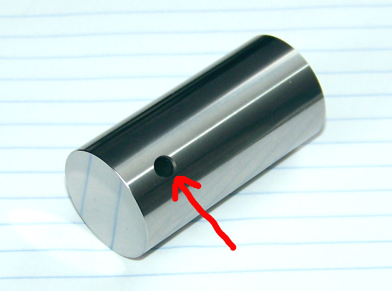
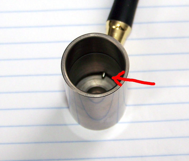
I've taken some photos to illustrate the design feature being discussed. The tappet in the photos is a tool steel tappet we manufacture for Triumph TR3/TR4 race engines, that we included the drainage hole in (without any critical thought at the time as to whether it actually did any good).
Exterior View:

Interior View (note the tip of my pen):

Thanks,
Kai
This is for an OHV engine with a pushrod valvetrain. The tappets do not have pressurized oil feeds, they only receive drainback oil from what was delivered to the rocker assembly. BMC/British Leyland started to include these oil drain holes on the sides of the buckettappets in the late 1960s. I am designing a tool steel tappet and need to make the decision about whether to include these oil drain holes or not. I seem to be the only detractor in our office. My thoughts:
1) Because there is no mechanical link between the tappet and camshaft, the location of the oil drain back hole is only optimal at any given time by pure chance. One would suggest then that rather than having a single drainage hole, that a greater number of smaller drainage holes (2, 3, 4?) would provide a more regulated discharge with a greater chance of dumping the oil on the actual camshaft lobe.
2) How can the tappet possibly be stationary long enough, in its vertical stroke, to collect any oil to reasonably perform the intended job of the drainage hole? Perhaps at extremely low engine speeds (idle), there is enough time for the tappet to sit rather still on the base circle of the cam and allow for the steady collection and discharge of oil... but oil delivery volume to the rocker assembly, and therefore drainage down to the tappets for collection, will also be at its lowest at idle. At higher RPM, the tappet must be moving through its stroke with such changes in acceleration that it surely must do a better job flinging the oil back up the lifter bore rather than collecting it and delivering it through the drainage hole when the tappet settles back down on the camshaft base circle.
3) On most of the engines I have seen with this type of tappet with the side drainage holes, there are still other avenues of drainage that allows the oil runoff from the rocker assembly to by-pass the tappets as the drainback route. In order to increase the volume of oil that could be caught and drained through the tappets, those other avenues of drainage from the rocker assembly should be blocked/restricted.
So overall I'm skeptical that this design feature actually does anything positive. I would love to hear other comments and if anyone (Greg Locock?) knew of any studies from the 60s/70s/80s done by the major manufacturers of the time, that input would be much appreciated.
I've taken some photos to illustrate the design feature being discussed. The tappet in the photos is a tool steel tappet we manufacture for Triumph TR3/TR4 race engines, that we included the drainage hole in (without any critical thought at the time as to whether it actually did any good).
Exterior View:
Interior View (note the tip of my pen):
Thanks,
Kai
