Eng-Tips is the largest engineering community on the Internet

Intelligent Work Forums for Engineering Professionals

Tech advice needed in reverse engineering rotor of DC torque motor

Status
Not open for further replies.

FHAvant

Mechanical
Jun 23, 2021
9
0
0
PK
Good day to everyone.
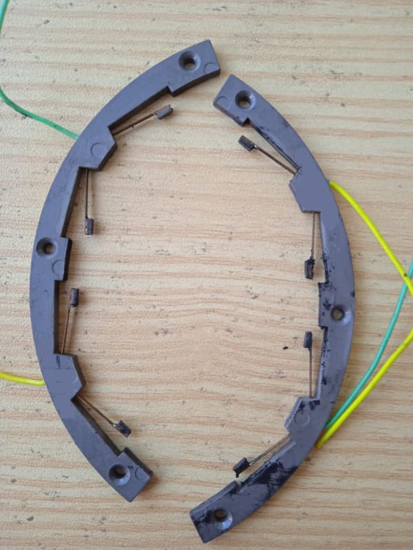
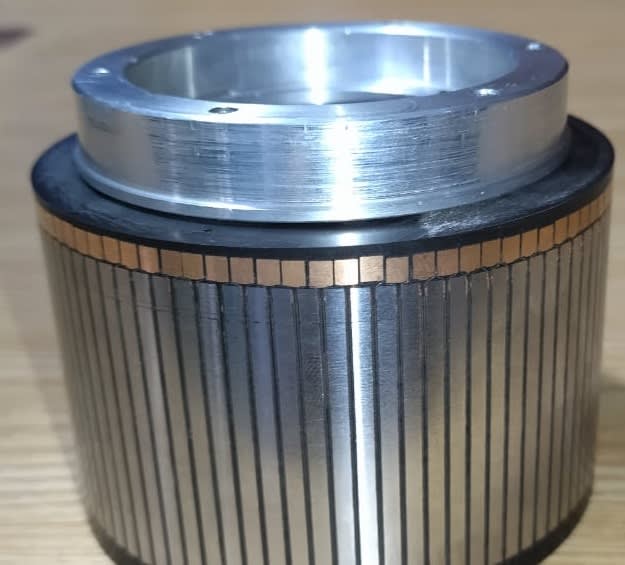
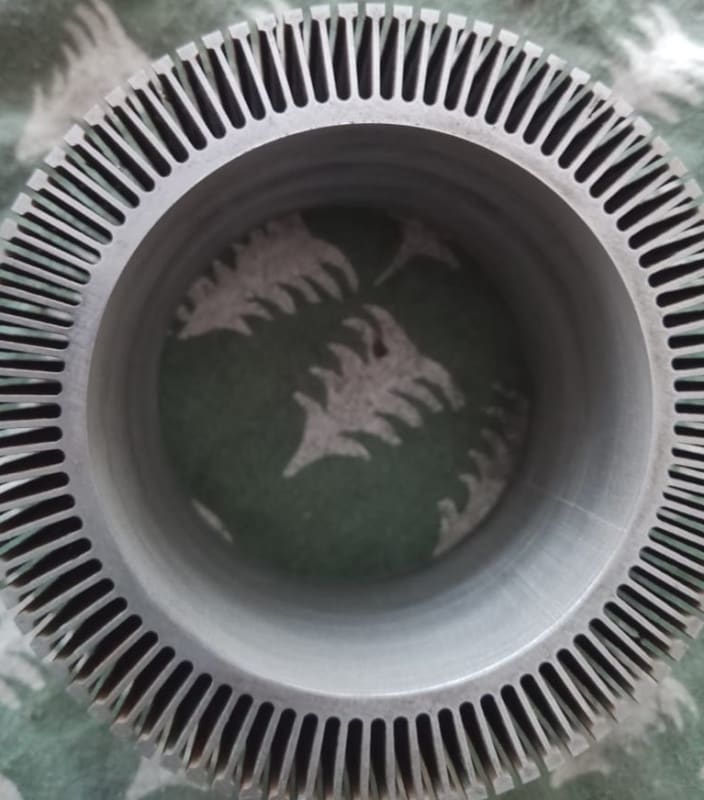
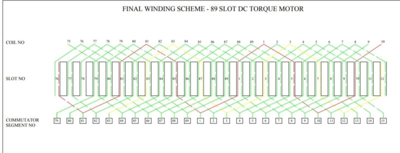
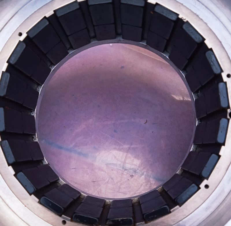
I am working on repair of a 50 v DC torque motor. It is used within a digital feedback control system for precise positioning of an arm. The angular position is given by a synchro resolver to control system. The rotor's winding was burnt and a new rotor was needed since the winding was fully concealed in potting epoxy.

The winding scheme / wire gauge of motor’s rotor was reverse engineered by me from original rotor. I used two parallel coils of # 33 gauge wire between commutator segments, as in original rotor. The core of the rotor was made using wire erosion / cut process on a stack of 0.5mm electrical sheet. After soldering the coils with commutator segments, the winding was potted using electrical epoxy and brought to final diameter size by grinding process. Kapton sheet was used as insulation in slots / between commutator segments. Photographs of winding diagram, rotor core, permanent magnet stator and finished rotor are shown for reference.

The developed rotor has performed well and gives similar RPM (200-300 rpm at full voltage) but there are two problems. The starting voltage of repaired motor (with new rotor) is higher now as compared with original rotor. The starting current is also higher. The original motor started moving at less than 1.0 vdc at 0.1 Amp current, whereas the repaired motor starts at approx 7.0 vdc with higher current of 0.25 – 0.5 amps. Secondly, the repaired motor has less torque than original motor. No other items in the motor were changed in addition to developed rotor (i.e carbon brushes, permanent magnet stator, bearings / covers / fittings etc).

Pl advice what can be done to achieve a smaller starting voltage and better torque.
WhatsApp_Image_2022-09-22_at_13.02.22_caif2h.jpg
IMG-20220324-WA0053_foddk7.jpg
IMG-20220520-WA0027_qzhgjw.jpg
WhatsApp_Image_2022-09-22_at_12.49.03_i0f5ej.jpg
IMG_20211127_114507_o402vj.jpg
 
Replies continue below

Recommended for you

@Panther.
No; Both the carbon brush rings are fixed with two screws on the body of stator shell (holes visible in stator pic) and cannot be fixed in another position. I have cleaned up the carbon brushes etc, but not altered its geometry at all. The OEM has specified a certain range of Ohmic value (6-8 Ohms) which should be available at two terminals (yelow & green wires) of carbon brush when the motor is assembled with carbon brushes. OEM also specifies that this value should not have a variation of more than 1 Ohm, as the rotor is moved slightly and carbon brushes touch another set of commutator segments. Our rotor / motor passes this test.

Can you suggest how to check if it is in a good neutral zone? I am assuming that it relates to the circuit made by the carbon brush contacts between certain commutator segments, as the rotor rotates. Or anything else that might be checked.

Looking forward to your reply.
Regards.
FHAvant.
 
FHAvant ,

There was often a question on the forum. The easiest way is to apply some less or all 50 V alternating voltage to the excitation winding and then measure voltage on the brushes. By moving the brush holder, the voltage should be set to almost zero . It seems to me that maybe when winding the rotor, the beginning of the winding is moved by one or more segment on the collector .
 
FHAvant: The brush neutral zone typically corresponds to the approximate center of a main pole: one polarity brush is located under a "north" pole, the other polarity under a "south" pole. The purpose of this placement is to ensure commutation occurs where there is the least likelihood of sparking. As the brush moves away (circumferentially) from this location, sparking becomes more prevalent. The spark will appear on the side of the brush that corresponds to the real neutral plane (i.e., correction requires moving the brush TOWARD the spark). The worst case occurs when the brushes are at exact opposite polarities (the "north" brush appears under a "south" pole, for example). When this happens, any amount of load current will induce terrific sparking - even the nominal "no load" condition, although that is not always the case.

If the winding is a bit off with respect to the commutator segment location, the neutral plane may be shifted slightly from the original design. Typically this means your end connection is not centered on the coil span (may actually be off by a bar or more). As noted above, the further from true neutral the connection, the more sparking is apparent.

In a DC motor, developed torque is proportional to both rotor (armature) current and strength of magnetic field (field flux), with some "K" factor that is related to basic geometry constraints (number of poles, circumference, slot geometry, radial airgap, etc.). Depending on what happened to the motor to create a need for a rewind, several things can be at work. The most obvious is that effective turn count in rotor winding is low, resulting in increased current to produce torque. Also shows up as low resistance in circuit. Another possible case is damage to either lamination steel or permanent magnet material, requiring more magnetic flux to "push" through the bad spot - again, more current required.

Converting energy to motion for more than half a century
 
Thanks Gr8blu and Panter. I will look into the winding scheme and number of turns again, to verify that I am not doing anything wrong. Will get back if I find something interesting. Regards. FHAvant.
 
OP said:
brought to final diameter size by grinding process.
Air gap? The air gap is more important than the actual diameter. Increased air gap is bad.
Neutral zone? If you can't move the brushes, remove them and use the probes of a meter at 180 degrees. The null point is the neutral point where the brushes should be centred.
Neutral zone if the motor has a permanent magnet field. With the motor running at moderate speed and moderate load: Sparking/arcing at the brushes. The brushes should be moved to cover the sparks. A generator under moderate load, again cover the sparks.
It's been a lot of years but I have used both methods successfully.
I suspect a neutral zone issue. I anticipate you will slot the brush holder mounting holes.
Another possibility, your electrical sheet may not have the same characteristics as the original iron.
You may have made the slots in the stator iron wider than the original.

--------------------
Ohm's law
Not just a good idea;
It's the LAW!
 
Your motor is supported by a cutlass bearing? Is it oil filled? Have you considered the lubricating oil as a culprit? Those poles look to be coated in rubber which would indicate that they are a bearing?
 
Status
Not open for further replies.
Back
Top