Continue to Site

Eng-Tips is the largest engineering community on the Internet

Intelligent Work Forums for Engineering Professionals

  • Congratulations KootK on being selected by the Eng-Tips community for having the most helpful posts in the forums last week. Way to Go!

Technical Information when Starting Electric Pump Motor

Status
Not open for further replies.

IOC-AUS

Electrical
Jun 10, 2021
17
Hello All,
I am new to the forum and joined to see if I can learn more about calculating Technical Data when Starting Electric Motors on Water Pump systems.
Have been exposed to various Starting methods including DOL (generally LRC is 6x times FLC) and VSD / Soft Starters (Changing Frequency/ Speed/ Voltages).
Is there a way to calculate the expected In-Rush Current of an Electric Pump Motor based upon Varying Frequency and Voltage.
We have built and supply a range of Variable Speed Generators (use Speed Actuator on Engine for 1300rpm thru 1800rpm + AC Generator with Special AVR + Pump & Generator Controller working in unison to Start and Protect Electric Pump Motors without VSD or Soft Starter- eliminate Harmonics, RF Filtering, Screen Cables etc.).
Our Generator Output Supply ranges from approx. 350V 43Hz (1300rpm) thru 415V 50Hz (1500rpm) thru 470V 60Hz (1800rpm).
We successfully have Started Electric Pump Motors (similar to DOL) by Ramping UP to eg. 1750rpm and Engaging AC3 Rated Contactor to manage In-Rush and Start Motor (AC Generator is suitably Oversized to support 60Hz Rated Output and Motor Starting Demands).
What we are trying to calculate is the possibility to Start the Pump Motor at lower Speed (eg. 1300 rpm 43Hz) - where our Voltage is approx. 350V.
Is it possible to consider and calculate the Starting Demands at the Lower Speed and Output Power.
My apologies for a long message but some background information is a key part of the questions.

Any Technical information and advice that is applicable and can help us better analyse the Low Speed Starting viability would be greatly appreciated.

Kindest Regards, Ian.
 
Replies continue below

Recommended for you

Since you are maintaining V/Hz at 360V/43 Hz, it should easily start with the same no-load current. For the entire range of speed, as long as you maintain the rated V/Hz, the no-load current of the motor remains the same, which is normally about 30 to 35% FLC for 4 pole motors.

Muthu
 
First, you must not exceed the motor Volts per Hertz curve for best results.
Most of the motor current is dependent on the rotor frequency, often called the "slip frequency".
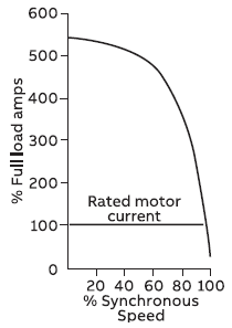
Look at the motor starting current curve.
At zero RPM, the slip is 60 Hz or 1800 RPM. At a rated full load speed of 1750 RPM, the slip is 50 RPM or 1.7 Hz.
Here is a starting current curve from the Cowern Papers.
image_hmv2qn.png

At 1300 RPM you are at about 72% of synchronous speed and the slip is about 28%.
The portion of interest of the current curve is to the right of 28%.
We are interested in the slip speed or frequency. You must reverse the numbers across the bottom of the curve. Zero percent speed equals 100% slip. 28% speed equals 72% slip.
At first it may seem as if the reduced frequency and voltage have made little difference, but the curve is in percent, not absolute values.
The applied voltage is about 74% of rated voltage so the current may be expected to be about .74[sup]2[/sup] or 55% of the normal starting current.
The short answer, your starting method will reduce the starting current by about 55% or around 300% of full load current rather than 600% of full load current.
This estimate is for the initial starting surge to accelerate the motor to 1300 RPM.
The current as the generator accelerates from 1300 RPM to 1800 RPM will depend on the rate of acceleration.
If you drop your initial generator speed down to 1000 RPM, your starting current may be less than 200% of rated full load current.
A tip on generators.
The standard speed for islanded generators is 1854 RPM or 61.8 Hz.At full load, the speed and frequency will drop to 1800 RPM and 60 Hz.
However, with a dedicated load I have no issues with trimming the speed and frequency to 1800 RPM and 60 Hz at full normal load.

Bill
--------------------
Ohm's law
Not just a good idea;
It's the LAW!
 
The applied voltage is about 74% of rated voltage so the current may be expected to be about .742 or 55% of the normal starting current.

But it's not 74% of the rated voltage. The frequency is also reduced and the rated voltage follows the frequency reduction. If you take a motor and apply 1/2 the nameplate frequency then that motors operating voltage is also 1/2 of the nameplate voltage. If 470V/60Hz is the final operating point, then 337V is the rated voltage for the motor at 43Hz.

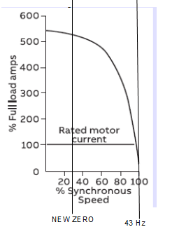
My guess right now is that you'd just slide the curve to the left the percentage of frequency reduction. @ 43Hz, 28% on the curve becomes the new 0% speed, or the motor operates on the curve from 28% to 100% equaling 0Hz to 43Hz or 0rpm to 1290rpm.
 
Lionel said:
My guess right now is that you'd just slide the curve to the left the percentage of frequency reduction. @ 43Hz, 28% on the curve becomes the new 0% speed, or the motor operates on the curve from 28% to 100% equaling 0Hz to 43Hz or 0rpm to 1290rpm.
That's what I was trying to say. Thanks for the additional explanation.


Bill
--------------------
Ohm's law
Not just a good idea;
It's the LAW!
 
I couldn't understand what you were trying to say about the curves.

So, what about the current @ 43Hz? A VFD just slides the curve, it doesn't reduce the current curve. This generator is doing the same thing. I'm thinking the 0rpm inrush @ 43Hz to be the same as the 28% speed inrush @ 60Hz.

I can say with complete certainty it won't reduce to 55%. With a fixed 60Hz, the torque is the parameter that reduces by the square of the voltage or by the square of the current. The torque would be 55% @ 74% rated voltage only if the frequency remained 60Hz. The current would be 74% @ 74% rated voltage only if the frequency remained 60Hz. Neither of these will be true with the frequency at 43Hz.
 
Yes Lionel I did make a mistake. I was going by a chart for reduced voltage starting methods, but it was unclear that the chart showed running current, not starting current. Possibly for centrifugal pumps.
(My source was the Cowern Papers)

Bill
--------------------
Ohm's law
Not just a good idea;
It's the LAW!
 
I think "100% synchronous" must be when the motor synchronizes with line frequency.
Zero speed = Zero% synchronous, so starting current is not changed with this scheme for DOL starting, regardless of frequency.
As long as the generator does not trip or stall on motor start, this should work OK on a pump or fan, providing the AVR is programmed to follow volts per Hz as discussed above.

I do not think this scheme would be appropriate for a constant torque application, like a hoist.
 
FacEngrPE; You can't scale the curve. You must truncate it on the left side.
For a VFD
The easiest way to visualize it is to change the % of synchronous speed to slip RPM or slip frequency.
The numbers will then increase in the other direction.
Zero speed becomes 60 Hz slip or 1800 RPM slip.
Find the slip RPM or slip Hz that is of interest and discard the part of the graph to the left of that.
For a VFD, you may be left with the portion that was originally from about 1700 RPM to 1800 RPM.
On a 1750 RPM motor that corresponds to about 200% load to no load, at any speed.
This is assuming that the VFD is set to a 200% current limit.
For this application, discard the portion of the curve to the left of 43 Hz SLIP.
And yes, the reduction of starting current will not be reduced very much, but the starting load on the generator will be reduced as the kW demand will be less. (I am still backing away from the chart that originally mislead me.)

Bill
--------------------
Ohm's law
Not just a good idea;
It's the LAW!
 
image_zgo0so.png


Bill
--------------------
Ohm's law
Not just a good idea;
It's the LAW!
 
Thanks so much for all of the replies and Technical information and Curves.
I will need to read through the thread a few Tinmes to best absorb the information.
A key ingredient in our Variable Speed Generator is to eliminate Costs and Harmonics associated with VFD & Soft Starters. Taking away these items also removes the Reduced Starting capabilities and we now need to manage Starting via 'traditional' DOL. We carefully size AC Generator to manage Starting demands and use Engine Speed to provide short term increase in Ouput Rating + some flexibility in Operating at different Duty Points (mainly targeting the Punping & Irrigation sectors) - In General, we have an approx 10% difference from Nominal Generator Set Rating (ie. 100 kVA Rated Genset @ 1500rpm 415V 3 Phase 50Hz will be capable of 90 kVA @ 1300rpm 350V 43Hz OR 110 kVA @ 1800rpm 470V 60Hz).
From my initial review it seems that Starting at Low rpm (43Hz) will gain a small reduction in % of LRC and a benefit with a reduced Load on the Generator.
We will need to be sure the GenSet is capable of getting the Motor away at the lower speed.

Much appreciate this thread and the input from those who have contributed - always learning and these topics help to fill in some gaps of knowledge that are not so clear for me.
I realised during my research that many other related elements come up such as:-
● Motor Slip (some light has been shed on Slip rpm or slip Frequency in the above responses)
● Flux
● Fan Speed for Cooling (can be a problem at low speed longer running)
● Torque
● In-Rush Current and how it differs to LRC
● Harmonics and Waveform Distortion (particularly associated with VFD & Soft Starters)

Knowledge is something that is gained over many years from many people collaborating together- this forum is an excellent platform and I pass on my appreciation to all.
Kindest Regards, Ian.
 
Have you considered connecting the motor to the generator before starting the generator.
You would have to use a UPS to energize the AVR. You should also check how the UFRO function of the AVR acts at very low frequencies.
You mentioned in-rush current as separate from LRC.
Many times the term "In Rush" is used to describe LRC.
Yes there may be a transient current surge when a motor is energized, but it is so short lived that it is ignored by most protection devices, transformers, generators and by analog ammeters.
We never saw that transient in the field before the advent of digital ammeters.

Bill
--------------------
Ohm's law
Not just a good idea;
It's the LAW!
 
Hi Bill,
Can you elaborate more on the comment about connecting Motor to Generator before Starting the Generator (and UPS for Power to AVR).
Not exactly sure what you mean by this.
 
waross Tables are easier to read when the axis is labeled correctly. % slip is not the same as % synchronous, as % slip will add in the impact of torque (inertial and shaft). Of course this only matters for a case like this where the power supply has varying frequency. Thankyou for reminding me.

I like your idea of starting the generator with the generator solidly connected to the motor, with already having a Voltz/Hz AVR the only real issues are capturing every component that needs to be powered on a black start, and ensuring the generator has enough low end torque to not stall, and accelerate to operating speed fast enough that neither the motor or the generator overheat. It helps that centrifugal pumping torque is always small at low shaft speed.

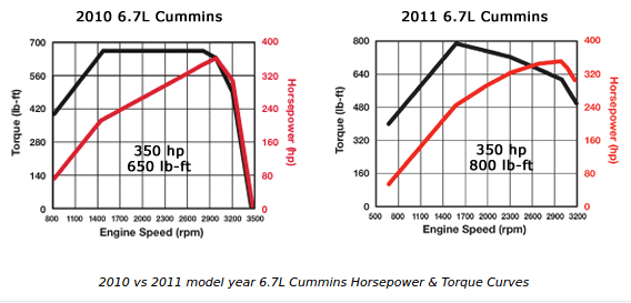
This is an example, use the torque curve for your diesel.
Screenshot_from_2021-06-11_04-43-50_lx7hcy.png
 
Hi Lionel.
Torque is determined by percent slip rather than percent of synchronous speed.
If we take synchronous speed as the output of the VFD, the curve is valid at only one base speed.
Torque is fairly constant at a given slip in Hz or RPM, not as a percentage of base speed.
Converting the curve labels from percent synchronous speed to slip in RPM or Hz is a straight substitution at rated frequency.
The advantage is that with the table now labeled in RPM slip the table may be used for any base speed or frequency.
Hi IOC-AUS
A couple of basics first;
Consider a motor rated at 1750 RPM. That is 50 RPM below synchronous speed or 50 RPM slip.
At full load, the slip will be 50 RPM.at 200% load the slip will be about 100 RPM. It gets non-linear at higher slips.
Also, at 50 RPM slip, the motor will be drawing about full load current, at any base frequency or RPM.
Next, an important factor or limit for inductive loads with magnetic cores is the saturation point. This is frequency and voltage dependent. At a given frequency as the voltage is increased, the magnetic flux increases until the core is saturated. Once the core is saturated, further increases in voltage cause a disproportional increase in current and burnout may be the result.
So for a coil designed for 120 Volts and 60 Hz, the ratio of the Voltage to the frequency is 120 V / 60 Hz or 2V/1Hz.
At 30 Hz the safe design voltage is 60 Volts.
This V/Hz ratio is important for both motors and transformers.
When these components are converted between 50Hz and 60Hz, the safe voltage changes in the ratio of %0Hz/60Hz.
Now back to generators. Modern AVRs have a feature called Under-Frequency-Roll-Off. This typically becomes active at 47Hz or 57 Hz depending on the base frequency. If you have ever set up an AVR you may have noticed a jumper labeled 50Hz, 60Hz. That is setting the UFRO.
Before UFRO was incorporated, if a heavy load caused the set to slow and the frequency to drop, the AVR would hold the voltage at the set point and if the Volts per Hertz went too high, motors and transformers would saturate magnetically with a further increase in current and possible burnout of equipment, not to mention the added load on an already overloaded set.
Then UFRO was introduced. This reduced the set voltage as the frequency drops. This lowers the kW and KVA demands on the set and assists in speed recovery.
UFRO often becomes active when starting large motors. Any time the set frequency drops below 57 Hz, UFRO is dropping the voltage to aid in recovery.
I hope that you are noticing a similarity with a VFD. As the frequency drops the effective voltage drops.
It is theoretically possible to start a centrifugal pump with less than full load current up until the pump curve catches up and the pump starts to work in the last few hundred RPM of acceleration.
Proposal:
Select an AVR with the UFRO active down to very low frequencies.
Use a UPS to power the AVR, the motor starter and any other devices that must be powered up when the motor starts.
Start the engine.
As soon as the engine starts to run, it will start to develop a low frequency output. The UFRO should reduce the voltage so that the proper V/Hz ratio is maintained.
The action may be similar to a VFD ramping up the starting voltage and frequency of a motor.
Possible pitfalls.
The acceleration rates of the diesel engine and of the motor and pump will be important. If the pump motor is able to accelerate as fast as the diesel engine, your chance of success is good.
If the diesel engine is able to accelerate much faster than the pump motor the results will not be as good.
Try it and see.
On the one hand you may be able to reduce the size of generators needed, on the other hand, this may not be for every customer.
In the event that a customer does not understand the system and changes some settings or bypasses some components the set may not be able to start a pump.

Bill
--------------------
Ohm's law
Not just a good idea;
It's the LAW!
 
Status
Not open for further replies.

Part and Inventory Search

Sponsor