Eng-Tips is the largest engineering community on the Internet

Intelligent Work Forums for Engineering Professionals

  • Congratulations waross on being selected by the Tek-Tips community for having the most helpful posts in the forums last week. Way to Go!

Tee Vent with Bevelled Ends for Natural Gas Emergency GTG vent

Status
Not open for further replies.

notsocommonsense

Petroleum
Jul 2, 2008
10
0
0
CA
Hi,

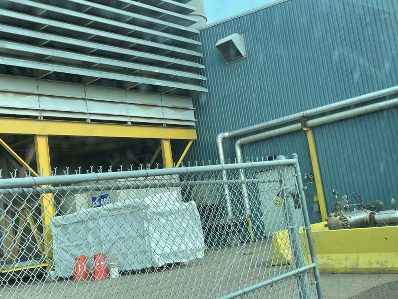
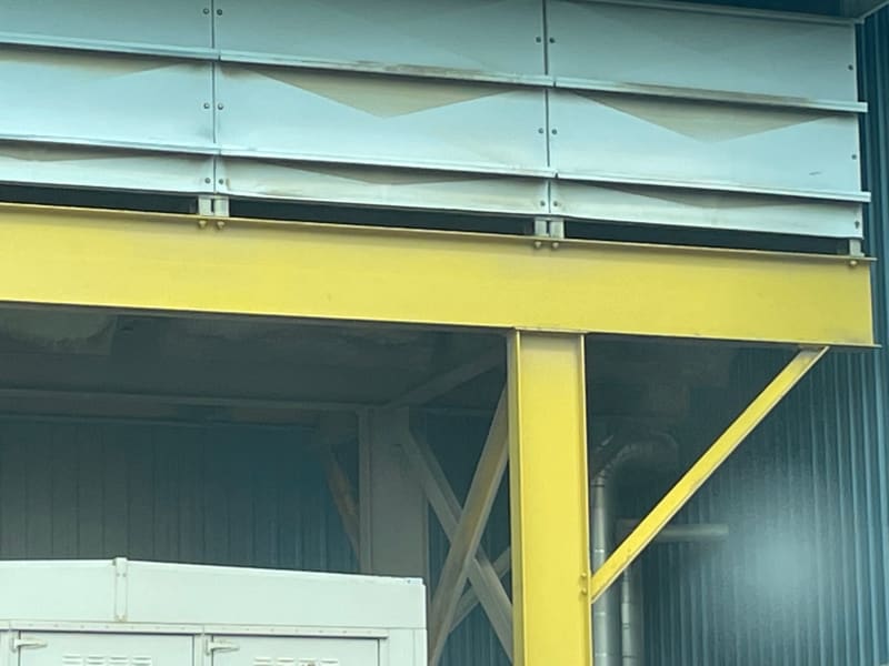
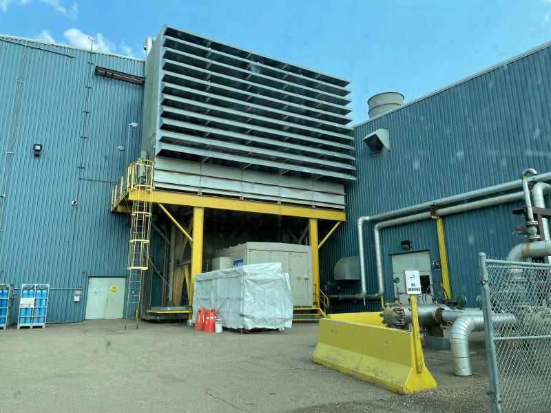
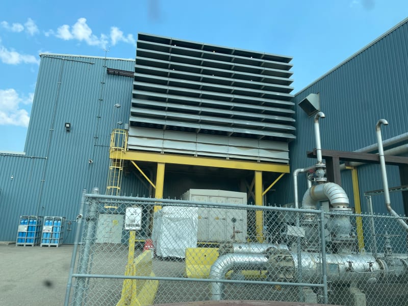
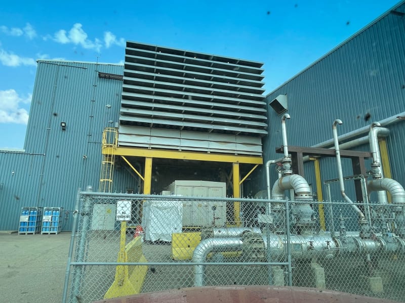
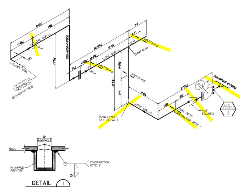
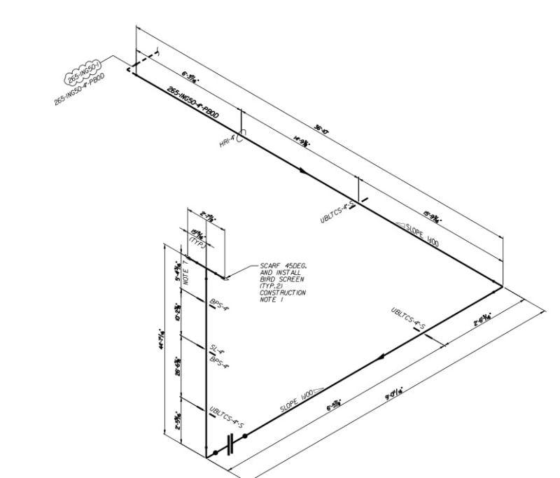
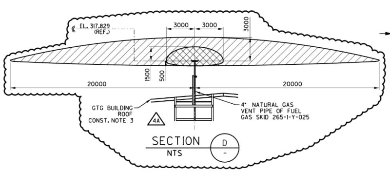
We have designed a 4" bi-directional discharge (tee with 45 bevels facing down with bird screens). The pipe extends 10 feet above a 40 foot roofline. There is a GTG air intake that starts another 10 feet below that. Our dispersion specialists have told us that this is adequate.

Couple of questions - WIth this arrangment, I don't think I need to worry about any serious moisture making it into this system. There is about 150 feet of pipe between the emergecy vent valve and the outlet. They wanted to put a weephole at the very bottom of this arrangment but there is about 80 feet of horizontal pipe and I just don't see it as being an issue as far as water goes. I am more concerned about the air intakes to the GTG (Gas turbine) but do I need to be concerned about that. I would think that 20 feet of vertical space should be enough, but will those 45 degree bevels cause a signifcant amount of gas to make it down that far before it scatters? The ends are facing sideways in both directions away from the intake.

Thanks in advance

If you haven't confirmed it with your own research, don't repeat it!
 
Replies continue below

Recommended for you

A plan and section views would be useful with some dimensions as well as what velocity of gas you expect out of the vent.

Also it's always best to use full words the first time rather than assume everyone else knows your abbreviations. GTG? Got to go? Gas turbine generator?

Why the 45 degree bevels?


Remember - More details = better answers
Also: If you get a response it's polite to respond to it.
 
No need for weephole for emergency vent in this case unless it can be shown that natural gas water or hydrocarbon dewpoint at atmospheric pressure is higher than daily minimum normal atmospheric temp. Or if retrograde condensation is possible. Weep holes are usually installed on PSV discharge lines if required; not on operational vent lines, assuming vent gas dos not condense in vent line. Besides, you've got the 45deg downward cut to prevent rain ingress into the vent line.
You say vertical gap between NG vent and turbine air intake is 10ft; what about horizontal distance between the 2?
Did the dispersion specialist account for all wind stability classes?
What criterion did the specialist use to say distance between the 2 is okay ? 25% LEL or less? What is the worst case LEL?
Is there H2S in this natural gas?
 
Thanks folks for taking the time to answer. Trying to answer your questions below. Hope I got 'em all.

LittleInch:

GTG - Yes - Gas Turbine Generator

45 degrees bevel to minimize sideways driven precipitation from entering the line.

ISO attached.

ISO-Part_1_nf4c9g.jpg
ISO-Part_2_wys2wj.jpg


georgeverghese

Well the air intake is about 10 feet wide and the vent pipe runs right up along side one edge of the intake. So basically the vent is right above the intake. No H2S. We were using 1.5/F and 5/D category.
The attached drawings show the vent at 1.5 m above the roof but its actually 3 m above the roofline.

ISO_model_view_hzzmga.jpg
release_view_-_HAC_Dwg_ihlf25.jpg
Dispersion_-_Elevation_View_npgx8f.jpg


If you haven't confirmed it with your own research, don't repeat it!
 
If memory serves me right, there are LEL detectors on turbine air intakes in cramped locations, with settings at 1oo3 voting 25% LEL for alarm and 2oo3 voting at 50% LEL for turbine trip. Your dispersion plot is only for 50% LEL, what about 25% LEL. And 1.5m/sec at F class stability seems high, what about lower velocity ?
Dispersion plot shown is for side view, what about dispersion plot for top view with air intake location shown?
So, preferably, at low wind speed, gas concentration should be <25% LEL at air intake.
 
In low wind conditions has the analysis factors in the air going into the inlet. Gas turbines can use large air flows and at such a local level you would think that the gas dispersion is impacted by the air inlet.

Remember - More details = better answers
Also: If you get a response it's polite to respond to it.
 
Good point @LI, would then suggest that notionally, we go for at least 10% less LEL at low velocity wind stability class for controlling case plot; ie <15% LEL to account for induction effect that would possibly distort the dispersion plume shape.
 
Thanks again for responding.

plan_view_dispersion_xkpnxe.jpg


So if 1.5 is no low enough, what would you suggest? This is what the guys that run these models here for us all the time suggested to use. Would the qualification of "low" depend on local average wind speeds?

I will ask our support to open up the model and run it again at 10% and 25% of LEL and see if there are LEL detectors there. Wondering what you would suggest as a low wind speed. This vent is our emergency vent to evacuate the line upstream of the turbine gas inlet block valve and an upstream valve. It is going to take approximately 15 seconds to vent. This in itself is not going to happen often. The more worrisome case for cloud formation is if the vent valve goes open by accident (water in wiring - whatever) but once again, the probability of that happening are much lower.

I was going to ask Siemens what they would recommend for a maximum concentration going into their unit. I am guessing that you are suggesting lower numbers as a safety margin. I have been away for a while and this project progressed without me. I am just reviewing now as the engineering packages have been issued. I have talked to the manager about getting rid of the weep hole already which we will progress.

Sounds like both of you guys have some back ground in this. Thanks for helping a guy out.

Yearn fer it, Learn it, confirm it, earn from it!
 
If you need some justification for wind speed/ wind class, ask for the annual wind rose at this location - the environmental engineers (or meteorologists if you have them in your Company) usually have this - choose the lowest wind speed that occurs at least 10-15% of the time.
Still not clear where the gas turbine air intake is exactly. All you've said so far is that is 10ft vertically down from fuel gas vent tip ( ie. z = -10ft). x and y coordinates not disclosed yet. Anyway, you've got our input, we leave the rest to you.
Also check that the thermal plume for the worst normal case hot GTG exhaust at autoignition temp does not impinge on the 50% LEL contour for this vent tip.
 
To be safe, would suggest an instrumented interlock : If the GTG fuel gas vent valve is not closed, turbine start to be inhibited. Probably costs next to nothing to do this, since you probably already have the vent valve status readout at the control panel .
 
Status
Not open for further replies.
Back
Top